

What are Lichtenberg figures, and how do we make them?(Last updated 05/05/22)

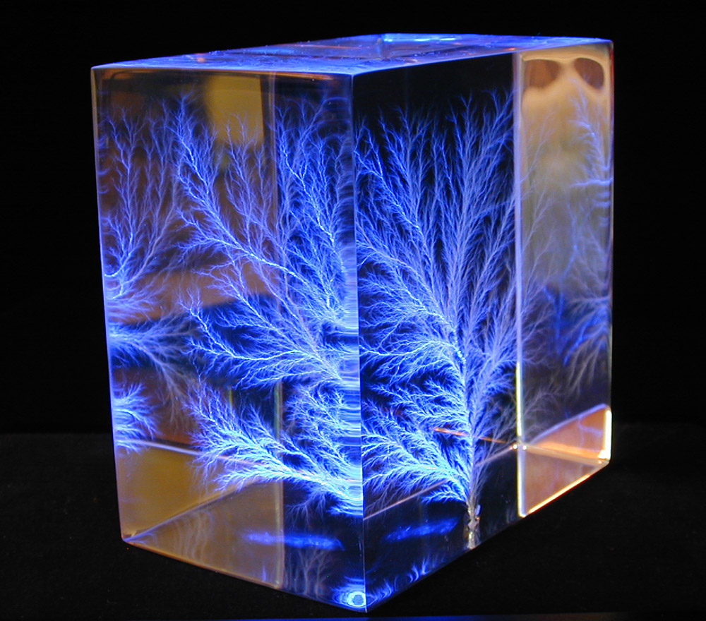
Doubly-Irradiated “Windblown Lightning” Sculpture
This Captured Lightning® sculpture was created by injecting trillions of
electrons into a block of
clear acrylic using a 5 million
volt particle accelerator. Electrons were injected into one side, the
specimen was rotated 180 degrees, and additional electrons
were injected through the opposite side. This created two
intensely-charged layers of excess electrons inside the specimen, each
located about
one-half inch below the
surface. The charge layer on the right side was then manually
discharged. The escaping electrons created a brilliant flash of
miniature “lightning” that propagated upward through the nearest
charge
layer. Additional discharges then grew from the right layer
towards the left layer, forming a complex, beautifully
interconnected 3D structure. The entire discharge took place in less
than 100 billionths of a second! The resulting sculpture above is
illuminated
from below
by blue light emitting diodes (LED’s). Each of our Captured Lightning
sculptures contains an incredibly detailed fractal-like discharge
pattern.
Unlike laser art, every one of our sculptures is a one-of-a-kind
treasure. As they
branch, the discharge channels become increasingly thinner. The
microscopic hair-like tips ultimately disappear into the acrylic. The
smallest
discharges are now thought
to extend down to the molecular level. See our Frequently Asked Questions (FAQ) or our one-page explanation for a quick overview of how these beautiful objects are created, or you can get all the details from this web page.
(Sculpture size: 3 x 3 x 2 inches or 7.6 x 7.6 x 5 cm)
What are Lichtenberg figures? A bit of history…
“Lichtenberg figures” are branching, tree-like patterns that
are created by the passage of high voltage electrical discharges along the surface, or inside,
electrically insulating materials (dielectrics).
The first Lichtenberg figures were actually 2-dimensional “dust figures”
that formed when airborne dust settled on the surface of electrically-charged
plates of resin in the laboratory of their discoverer, German
physicist Georg Christoph Lichtenberg
(1742-1799). Professor Lichtenberg first observed this in 1777,
demonstrated the phenomenon to his physics students and peers, and reported his findings in his memoir (in Latin): De Nova Methodo Naturam Ac Motum Fluidi Electrici Investigandi (Göttinger
Novi Commentarii, Göttingen, 1777). The English translation of the title is, “Concerning the New Method Of Investigating the
Nature and Movement of Electric Fluid”. Lichtenberg’s translated paper is contained in Appendix A of a Masters thesis by Mark A Payrebrune (“Experimental Morphology of Lichtenberg Figures”, McGill University, Montreal, Canada, 1979). The translated document (by Dr. J. Blain, Classics Department at McGill University) contains the following passage that describes Lichtenberg’s initial discovery:“At the beginning of spring 1777, after the completion of the new
Electrophore, everything in my little room was still covered with
extremely fine resinous dust that had settled, between the scraping and
the shaving of the instrument’s base or stand, on the walls and books.
As soon as a draft in the air arose, the dust fell, much to my
annoyance, on the conducting disc of the Electrophore. Often afterwards,
when I held the disc suspended from the ceiling of my room, it turned
out that the dust, as it settled on the base, did not cover it
completely, as it previously had covered the disc, but only in certain
areas. Much to my great joy, it gathered to form little stars, dim and
pale at first, but as the dust was more abundantly and energetically
scattered, there were very beautiful and definite figures, not unlike an
engraved design. Sometimes there appeared almost innumerable stars,
milky ways, and great suns. There were arcs, unclear on their concave
side, but radiant on their convex side. Very glittering little twigs
were formed, similar to those which frozen moisture produces on glass
window panes. There were clouds of different shape and shadows that were
visible in varying degrees … But the most pleasing sight
presented itself to me, when I saw that these figures could not be
easily erased, as I tried to wipe away the dust with a feather or a
rabbit foot. I could not prevent these same figures, which I had just
erased, from shining forth once more, and somehow, more brightly.
Therefore l placed a piece of black paper smeared with a viscous
material on the figures and pressed down lightly. I was able to produce
imprints of the figures, six of which the Royal Society has seen. [Note:
see figures below]. This new kind of Typography has been
extremely satisfying to me, hastening as I was to more remote
preoccupations and having neither the time nor the inclination of
sketching the figures or destroying them all.”During his subsequent studies, Professor
Lichtenberg used various high-voltage electrostatic devices to electrically charge
the surfaces of various insulating materials including resin, glass, and
ebonite (hard
rubber). He then sprinkled mixtures of finely-powdered
sulfur (yellow) and minium
(“red lead”, now called lead tetroxide) onto the
charged surfaces. He
found that powdered sulfur (which becomes negatively-charged by rubbing against its container) was more strongly attracted to
the
positively-charged regions on the surface. Similarly, frictionally-charged particles of
red lead acquired a positive charge and were attracted to
negatively-charged regions. The colored powders
made previously-hidden regions of stranded surface charges, as well as their
polarity, clearly visible. We now know that these charged surface regions
were previously deposited by small sparks of static electricity. The
sparks deposited isolated patches of electrical charge onto the surface
as they
flashed along the surface of the insulator. Once
deposited onto the insulator surface, the charges remain
stranded for a very long time since the insulator prevents them from moving and dissipating. Lichtenberg also discovered
that the appearance of
positive and negative dust figures was markedly different.
Discharges created by a positively-charged high-voltage
terminal were star-like, with long, branching paths while discharges from negatively-charged terminals were shorter,
rounded, and
fan-shaped or shell-shaped. By carefully pressing a piece of paper onto the
dusted
surface, Lichtenberg found that he could transfer the images onto a piece of paper,
demonstrating what eventually became the modern processes of xerography and laser printing. The underlying physics that created Lichtenberg’s dust figures evolved to become the
modern-day science of plasma physics.The
following demonstration video is a replication of Lichtenberg’s experiments
using a mixture of powdered lead tetroxide and sulfur to highlight positive
(yellow) and negative (red) Lichtenberg figures. In the video a Wimshurst electrostatic generator is used as the high voltage source instead of an electrophorus,
as originally used by Lichtenberg, but the principles are otherwise the
same. In the video, branching positive Lichtenberg figures are created first,
followed by shell-shaped negative Lichtenberg figures.
Many other physicists, experimenters, and artists studied Lichtenberg
figures over the next two hundred years. Notable 19th and 20th century
researchers included physicists Gaston Planté and Peter T. Riess (mid-1800’s). In the late 1800’s, French artist and scientist Etienne Leopold Trouvelot created “Trouvelot figures” – now known to be photographic Lichtenberg figures – using a Ruhmkorff coil as a high voltage source. Other researchers included Thomas Burton Kinraide (1890’s), and professors Carl Edward Magnusson, Maximilien Toepler, P. O. Pedersen, and Arthur Von Hippel
(1920’s-30’s). Most modern researchers and artists used photographic film to
directly capture the faint light emitted by the electrical
discharges. A wealthy English industrialist and
high voltage researcher, Lord William G. Armstrong,
published two beautiful full-color books showing some of his high
voltage and Lichtenberg figure research. Although these books are now
quite scarce, a copy of Armstrong’s
first book, “Electric Movement in Air and Water, with Theoretical
Inferences”, was made available through the kind efforts of
Jeff Behary at the Turn of the Century Electrotherapy Museum.
In the mid-1920’s, Von Hippel discovered that Lichtenberg figures were
actually created through complex interactions between corona discharges
or small electrical sparks, called streamers,
and the dielectric surface below. The electrical discharges deposited
matching patterns of electrical charge onto the dielectric surface
below where they became temporarily stranded. Von Hippel also
discovered that increasing the applied voltage, or reducing the
surrounding gas pressure, caused the length and diameter of
the individual paths to increase.
Riess discovered that the diameter of a positive Lichtenberg figure was about 2.8
times that of a negative figure of the same voltage. The relationships between the size of Lichtenberg figures versus voltage
and polarity were utilized in early high-voltage measuring and recording instruments, such as
the klydonograph,
to measure both the peak voltages and polarities of
high voltage impulses. A klydonograph, sometimes called “Lichtenberg’s camera”, could photographically record the size
and shape of Lichtenberg figures that were generated by abnormal
electrical surges on electrical power lines due to lightning
strikes. Klydonograph measurements allowed lightning researchers and power
system designers in the 1930’s and 1940’s to
accurately measure lightning-induced voltages, thus providing critical
information about the electrical characteristics of lightning strikes.
This information allowed power engineers to create
“man-made lightning” with similar characteristics under
laboratory-controlled conditions so that they could test the
effectiveness of
various lightning-protection approaches.
Lightning protection has since evolved to become an essential part of
the design for all
modern
electrical transmission and distribution systems. A schematic
diagram of the active parts of a klydonograph is shown on the leftmost
drawing below,
along with examples of klydonograms from positive and
negative
high voltage transients of various amplitudes versus polarity. Notice
how positive Lichtenberg figures are
considerably longer than negatives figure even though
the peak voltages are of equal magnitude.
A more modern version of this device, called a teinograph, used a
combination of delay lines and multiple klydonograph-like sensors to
capture a series of time-shifted “snapshots” for a given transient,
allowing engineers to capture the overall wave shape of a HV transient
event. Although they were eventually replaced by modern electronic
equipment, teinographs were still used through the 1960’s to study the
behavior of
lightning and switching transients on HV transmission lines.
Lichtenberg figures are now known to occur during the electrical breakdown of gases, insulating liquids, and solid dielectrics.
Lichtenberg figures may be created within billionths of a second (nanoseconds)
when dielectrics are subjected to very high electrical stress, or they may develop over years through a progressive series of small, low-energy, partial discharges.
Countless partial discharges on the surface or the interior of solid
dielectrics often create slowly-growing, partially-conductive 2D surface
Lichtenberg figures or internal 3D “electrical trees”.
2D electrical trees are often found along the surfaces of contaminated
power line
insulators. 3D trees can also form, hidden from view, inside dielectrics
due to the presence of small impurities or voids, or at locations
where an insulator has been physically damaged. Since these
partially-conductive trees can eventually cause the
complete electrical failure of the insulator, preventing
their initial formation and growth is critical to the long-term reliability of
all high-voltage equipment.
The study of electrical trees and their prevention has been critical to
the reliable design of the high-voltage power transmission systems that
transfer electrical power to our homes and businesses.3D Lichtenberg figures inside transparent plastic were
first created by physicists Arno Brasch and Fritz Lange in the late 1940’s.
Using
their newly-invented electron accelerator, they injected trillions of
free electrons into plastic specimens, triggering electrical breakdown and creatingcarbonized internal Lichtenberg figures. Electrons are tiny, negatively charged particles that orbit the positively-charged
nucleus of the atoms that make up all condensed matter. Brasch and Lange used high voltage pulses from a
multi-million volt Marx Generator
to drive a pulsed electron beam accelerator.
An article about their research and their accelerator (which they
called a “Capacitron”) originally appeared in the March 10, 1947 issue of LIFE
Magazine. The Capacitron could deliver a three-million volt pulse, and
could generate a powerful blast of free electrons with an incredible peak current of
up to 100,000 amperes. The glowing region of heavily-ionized air created by the exiting high-current
beam of electrons resembled a bluish-violet rocket engine flame. A complete set of B&W pictures,
including Lichtenberg figures inside a clear block of plastic, has
recently become available online, as has another article with color pictures
from the April, 1951 issue of Popular Mechanics. In 1944, Brasch
founded the Electronized Chemicals Corporation (ECC), a pioneering researcher of using electron beams to
cross-link monomers and polymers to improve their electrical and
physical properties. ECC was eventually purchased by the 3M Company in
1985.
The first formal scientific study of the injection and movement of electrical charges and charge trapping/detrapping within
dielectrics was conducted by Brazilian physicist Dr.
Bernhard Gross in the early 1950’s. Dr. Gross confirmed that internal Lichtenberg figures could be created within a number of different polymers
and glasses by injecting them with high-energy electrons from a particle accelerator. The
techniques that we use to make our modern sculptures are built upon the
theoretical work and experimental techniques originally developed
by Brasch, Lange, and Gross. 3D acrylic Lichtenberg figures are
sometimes called “electron trees” or “beam trees”. We call our
state-of-the-art creations Captured Lightning® sculptures.How do we make our Acrylic Captured Lightning® sculptures?
Since 2004, we have developed and refined irradiation and fabrication
techniques to create a wide variety of beautiful 2D and 3D sculptures.
We begin by carefully cutting and polishing various shapes from a clear, glass-like polymer called polymethyl methacrylate (or PMMA).
This material, commonly called acrylic, is sold under various
trade
names such as Lucite, Plexiglas, or Perspex (UK). Acrylic has a unique
combination of
high optical clarity and superior electrical
and mechanical properties. Besides being an excellent electrical
insulator,
acrylic is actually clearer than glass! We have tried a number of other
clear polymers, such as polycarbonate
(PC), polystyrene (PS) , polyester/polyethylene terephthalate (PET), epoxy, and clear polyvinyl
chloride (PVC). Lichtenberg figures can be made inside all of these
polymers with varying
degrees of success. However, the branches tend to be dark gray or even black instead
of the sparkling white, mirror-like figures seen within acrylic. We
have also experimented with making Lichtenberg figures in glass. However, since glass Lichtenberg figures often explosively shatter upon discharge or, unpredictably, days or even months later, we no longer make them.We inject electrons into acrylic specimens using a 5 million volt, 150 kW commercial particle accelerator called a Dynamitron.
The heart of this device is the accelerator tube – a huge three-story
high “vacuum tube” that operates at voltages between one and
five million volts. At the top of the tube, electrons are emitted by a
small, white-hot tungsten filament. The filament is connected to
the negative terminal of an adjustable multi-million volt power supply. The bottom of the tube is
connected to ground and the positive terminal of the high voltage supply. This configuration creates a very strong
electrical
field that accelerates electrons emitted from the filament. As they
“fall” though the large potential difference, and they acquire a very
high velocity. The
bottom of the vacuum tube has very thin (only 2.3 thousandths of an
inch thick!) titanium
window that separates the high vacuum on the inside
from atmospheric air on the outside. The high-velocity electrons pass
right through
the titanium window, almost as though it wasn’t there! Trillions of free
electrons emerge
through the outside surface of the window, travel
24 inches through air then crash into our acrylic specimens on the
moving carts below. Although the average lifetime of free electrons in
air is only 11 billionths of a second, that’s more than enough
time for them to work their magic on our acrylic specimens.
The energy of the accelerated electrons is measured in millions of electron volts (or MeV).
Most of our sculptures were created using electrons that had energies
between 2 and 5 MeV. At these energies, electrons are traveling at relativistic velocities – between 98.5% and 99.6% of the speed of light. During irradiation,
these energetic electrons burrow deep inside the
acrylic before finally coming to rest. The penetration depth is a
function of
the energy of the electrons in the beam, the target material’s
dielectric properties, and its atomic density. The charging process
is called “deep dielectric charging”. The higher the energy of
the electrons in the beam, the deeper they penetrate. For example,
electrons with an energy of five MeV will
penetrate about one-half inch into acrylic, but a 1/16-inch thick piece of much denser lead will completely block them.
When
a thick piece of acrylic is irradiated, huge numbers of electrons
accumulate
inside the specimen, creating a strongly-charged cloud-like layer called
a space
charge. Because acrylic is an excellent electrical insulator, injected
electrons become temporarily trapped inside the acrylic. By passing
thick specimens
through the electron beam in two or more passes, changing specimen
orientation between passes, or rotating them while they’re
being irradiated, complex 3-dimensional space charge regions can be
created inside the acrylic. As electrons accumulate during irradiation, the
electrical stress (called the electric field or “E-field”) inside
the acrylic dramatically increases, reaching several million volts
per
centimeter. We normally charge our specimens to just below the point
where they’ll break down. We then force the charged specimens to release
(“discharge”) the electrons at the desired location by poking them with a
heavily-insulated, pointed
metal tool. This creates a small fracture that greatly concentrates the E-field at that point. The intense electrical field at the tip of the fracture overcomes the dielectric strength of the acrylic, initiating complete electrical breakdown of the specimen. During breakdown, some of the chemical
bonds that held acrylic molecules together suddenly break, stripping away free electrons in a process
called ionization.
The newly-freed electrons become accelerated by the
extreme electric field, and as they collide with other
molecules, they rapidly create an ever-increasing number of new electrons in an exponentially-growing runaway process called avalanche breakdown.Within
billionths of a second, a tree-like network of white-hot plasma channels form within
the acrylic and, with a bright flash and a loud BANG, the
material undergoes complete dielectric breakdown.
The previously-trapped electrical charges rush out in a river-like
torrent. Thousands of smaller tributaries dump their
share of stored charge into larger channels that eventually merge into a
single, brilliant discharge path that exits the acrylic. Although images
and videos appear to suggest that we’re injecting high voltage into each piece, we are
actually removing the excess
charges that were previously trapped inside each piece. Dielectric breakdown occurs with incredible speed – the main electrical discharge
within a 4-inch square specimen lasts less than 120
billionths of a second (120 nanoseconds)! Some physicists think that dielectric
breakdown within a charge-injected solid may be the most energetic
(explosive) known chemical reaction.
The
following image shows a 12 x 12 x 1 inch
specimen being discharged. In the image, camera settings were adjusted
to reduce the brilliance of the discharge so that the individual plasma
channels can be
seen. Note the bright descending discharge that exits from the discharge
point, across the top surface of the specimen, and then to the groundedmetal table below:

(Photo courtesy of Terry Blake)
As the miniature lightning bolts blast their way through the acrylic,
they
create millions of microscopic tubes and fractures, leaving behind a
permanent “lightning fossil” deep inside the acrylic. The peak current
within the electrical discharge reaches hundreds, or even thousands of
amperes, depending upon the physical size of the specimen. The white-hot high-density plasma within the
confined discharge channels causes the nearby acrylic to vaporize
and fracture, and highest-current “roots” often char the surrounding acrylic. The
exit point of the discharge creates a small crater on the surface as hot gases explosively exit the specimen.
Surprisingly, although we inject a huge amount of negative charge into
our specimens, the electrical discharges originate from spark tips which aremore electrically positive (versus the space charge layer), so all of
our Captured Lightning® sculptures are actually “positive” Lichtenberg
figures! Single-discharge branched figures continue to split as paths
become finer, filling the charged area, but they never cross or form
loops. The finest tips eventually disappear into the acrylic.Some specimens self-discharge while they’re being irradiated by the
electron beam. This
is usually caused by a small surface scratch or imperfection, left-over
manufacturing or fabrication stresses, or an internal defect, such as a
small bubble or inclusion, inside the acrylic. A
self-discharged
specimen will continue to discharge numerous times while it is being
irradiated as the electron beam continues to inject new charge into the
specimen. Unlike the neatly-branched structures seen in
manually-triggered sculptures, self-triggered sculptures typically
develop a
thicker, mat-like tangle of chaotic discharges, or a complex combination
of
dendritic and chaotic patterns. Because of their complexity,
self-discharged specimens are often among some of our most fascinating
sculptures.
Video clip of a huge 15 x 20 x 2 inch sculpture being discharged:
Following
is a short video clip showing a huge 15″ x 20″ x 2″ specimen being
discharged. The specimen was first
charged on one side using a 5 MeV electron beam. The electrically-charged
specimen was then (very carefully!) flipped over and irradiated once
more on the other side. This created two independent charge layers,
each located about 1/2″ below the large surfaces. Prior to discharging,
the estimated potential of these internal layers was over 2.5
million volts. Because there were two very large charge layers, this
specimen stored significantly more electrostatic energy than most of our
other specimens – more than four kilojoules! Safety precautions were
necessary to prevent the possibility of receiving a painful, and potentially dangerous, electrical
shock.Although the main discharge is quite brief (under 500 billionths
of a second for this specimen), the video successfully captured the brilliance of the 4
kilojoule electrical discharge in a single video frame (shown below). Numerous
secondary discharges continued to intermittently flash after the main discharge. These
continued with decreasing frequency for over 30 minutes. This video is courtesy of
Dr. William Hathaway, GCL Laboratories. The resulting sculpture, cradled within
a custom walnut light base and illuminated by an array of white and
blue LED’s, is also shown below.
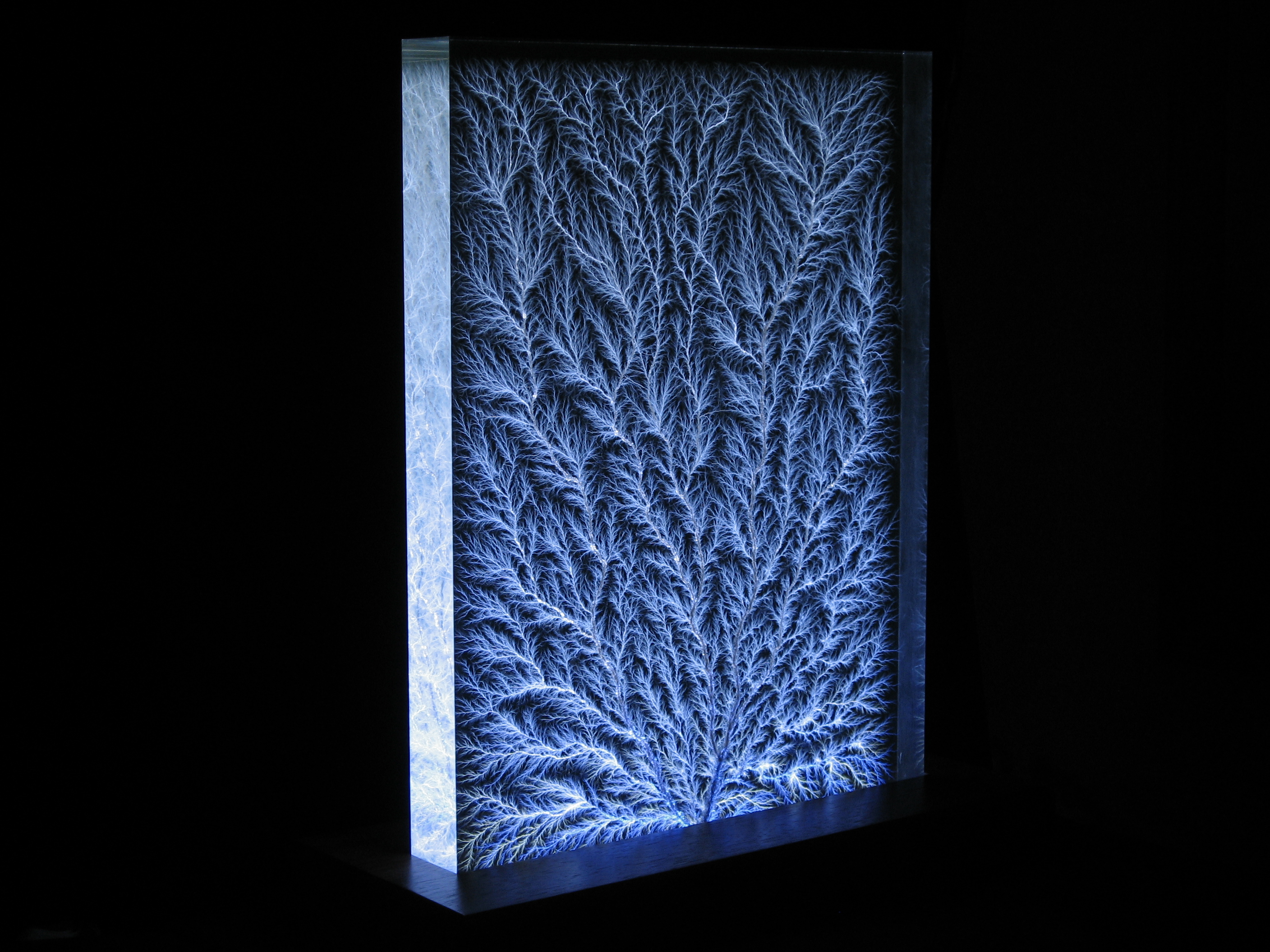
(Click on above image for high-resolution image)
The resulting Lichtenberg Figure is a series of branching hollow tubes surrounded by conchoidal
(shell-shaped) fractures. Conchoidal fractures are characteristic of the way that glassy (amorphous)
materials fracture when stressed beyond their breaking point. Since the
countless
fractures behave as tiny mirrors, illuminating a figure through the
edges causes the entire Lichtenberg figure to glow brilliantly
with the reflected colors of the external light source.
Lichtenberg figures have fractal properties
The
branching pattern of a Lichtenberg figure looks similar at various scales of
magnification. This property is called “self-similarity”, and it suggests that Lichtenberg
figures can be mathematically described through a branch of mathematics called Fractal Geometry.
Unlike most common geometric forms, fractal-like objects do not have
even-integer dimensions. Instead, they
have dimensions that lie between 1 and 2 (for 2-dimensional fractals) or between 2
and 3 (for 3-dimensional fractals). Lichtenberg figures
may be one of the first fractal-like forms created by man. Our
branching 2D Lichtenberg figures have a
fractal dimension that varies between 1.5 (for thin, sparsely branching discharges) to 1.9 for
dense, fern-like bushy discharges. Most of our standard 2D sculptures have a
fractal dimension of about 1.7. Our 3D sculptures typically have a fractal dimension of about 2.5.
The appearance of
the resulting Lichtenberg figures depends upon how much charge was injected into the
acrylic and where and when the specimens are discharged. The technical terms for branching figures are
dendritic or ramified (tree-like).
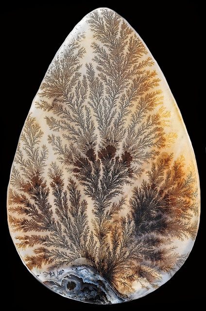
If a larger amount of electrical charge is injected
into a specimen, very dense dendritic discharges can be created such as
in Figure 1 below. These very dense discharges are similar in appearance
to fern fronds (“filiciform”) or plume agates.
Specimens exhibiting this
form were heavily charged to just below the point of self-breakdown and
then immediately discharged. If we reduce the amount of injected charge,
more classical, lightning-like or tree-like discharges are created
(Figure 2). If premature breakdown occurs while we’re actively
irradiating
a specimen, the resulting discharges form a thicker, densely tangled
mat of “chaotic”
discharges
(Figure 3). The fractal dimension of chaotic discharges is currently
unknown. In chaotic discharge specimens, after the initial breakdown,
newly-injected electrons from
the accelerator recharge smaller nearby regions, causing them to
repetitively discharge in random directions into existing discharge channels. The rapidly changing
internal electrical fields create a much thicker mat of densely chaotic
discharges that
are reminiscent of interconnected nerve cells and neural networks.
Some of the most complex and fascinating patterns
occur when a specimen self-discharges about halfway through the charging
process, creating dramatic discharges that change from being densely dendritic
to densely chaotic across the sculpture.
The
self-similarity of dendritic discharges can easily be seen in the
following sequence of zooms from a 12″ x 12″ Lichtenberg Figure.
Although the branches become finer and hairlike, the overall branching
structure remains similar until the finest tips ultimately disappear at
the very edges of the discharge structure. Some recent research suggests that this dendritic pattern may extend to the molecular level.
Similar fractal-like patterns are prevalent in nature. They are seen in
aerial views of rivers and their tributaries, and organic structures
such as branching tree limbs, your body’s circulatory system, and within
various organs such as lungs, kidneys, and the liver. The satellite
view in the left image below shows a river
drainage system near Grand Junction, Colorado, USA. The rightmost image is a
casting of the bronchial tree of a human lung (courtesy Paul Cazeaux,
PhD student at Laboratoire Jacques-Louis Lions (LJLL), Paris, France).
The similar branching structure of all of these systems may be a
consequence of a recently proposed new law of physics, the Constructal Law,
which states that Nature tends to develop a hierarchical branching
network of paths that result in most efficient flow. The flowing
material can be water, air… or even electrons!
Lichtenberg figures can be mathematically modeled using an iterative growth process called “Diffusion Limited Aggregation” (DLA). A more accurate model, that combines an electric field with DLA, is called the Dielectric Breakdown Model (DBM).
The DBM appears to accurately describe the forms of Lichtenberg
figures that occur under various electrical field intensities on the
surface or within solid, liquid, and gaseous insulators.
Other interesting properties: fluorescence, solarization, birefringence, and the discharge-free zone
When
acrylic is bombarded by high-energy electrons, it glows brilliantly
with a blue-white color. Radiation chemistry studies suggest that this
is mainly due to luminescence that peaks at a wavelength of about 435 nm. However, acrylic also generates fainter glows from X-ray fluorescence, and Cherenkov radiation
as high velocity electrons interact with acrylic molecules. The
detailed light-producing mechanisms for electron-irradiated acrylic are
not fully understood.
Newly-irradiated specimens develop a discolored layer in the region
between the irradiated surface(s) and the
discharge layer. This phenomenon, called solarization, appears to be caused by various interactions between the injected electrons and the molecular structure of the acrylic. During
irradiation, electrons in the beam are initially traveling at over 99%
of the speed of light. As they penetrate the specimen, they collide with
acrylic molecules, rapidly coming to a stop within a fraction of an
inch. Electrons in the beam have considerable kinetic energy,
and as they collide with
the atoms in the acrylic they release this energy
as heat and x-rays.
In acrylic, most solarization seems to occur in the regions directly
hit by the electrons. However, regions that are intentionally covered by sheet lead (to prevent
electrons from hitting some areas of the acrylic) may also exhibit
solarization within deeper regions of the acrylic. As electrons crash into
the lead mask, they radiate intense x-rays that apparently create a darker region of
solarization in the acrylic immediately underneath the mask.
Energetic collisions with electrons, x-rays, and the build-up of excess electrons stimulate chemical and
physical reactions that alter the physical and optical properties of the
acrylic. Deeply-trapped electrons may remain stranded within the
acrylic for several years. These create color centers
which also contribute to solarization. While some of these changes may last
for only minutes, others persist for months or years after
irradiation, and some appear to be permanent. Although all of the specific causes
of solarization are not completely understood, there is evidence that
irradiation creates longer-lived unstable (“metastable“)
compounds that preferentially absorb light at the blue end of the
spectrum (wavelengths between 250 and 400 nm). Since a portion of the
blue spectrum of ambient light
is absorbed by the solarized region, freshly-irradiated specimens
typically appear green, amber, or sometimes even rose-colored when
illuminated by white light.
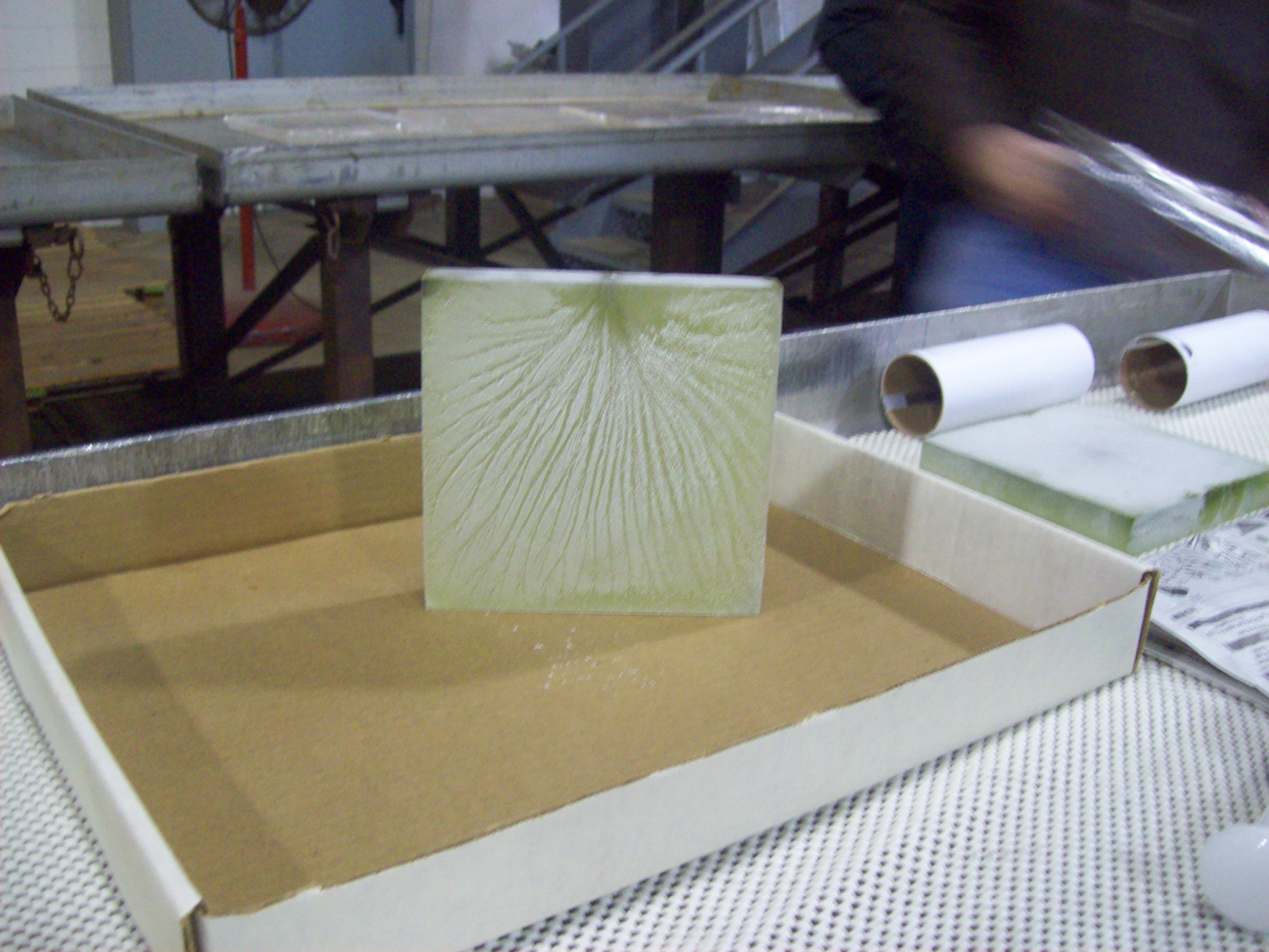
The solarization layer in charged acrylic specimens is most often lime-green immediately
after irradiation. Within minutes of being discharged, the solarized layer changes to
brownish-amber, then fades to a lighter amber color over weeks or months. The
amber region usually fades away over months to several
years. The fading process can
usually be accelerated by heating
the
block in the presence of air or by leaving the specimen
in bright sunlight for an extended period of time. As oxygen diffuses
into the
acrylic from the outside surfaces and the porous discharge layer,
it
slowly bleaches the solarized region, causing the solarized layer in between to
gradually become thinner until it eventually disappears entirely.
Most Lichtenberg figures older than 2-3 years are completely bleached. Although older
specimens may no longer show any solarization, many exhibit various
degrees of “fogging” from electron collisions and X-radiation damage to the acrylic’s molecular structure.
Some PMMA specimens exhibit
comparatively little initial solarization, while a small percentage of other
specimens permanently retain their amber color. Permanently-colored specimens
appear to be solarized via a different, deeper penetrating mechanism,
such as X-radiation, since these specimens also tend to be uniformly
solarized throughout their entire thickness. These differences may be due to
subtle variations in the acrylic blends and the specific catalytic agents used by acrylic manufacturers to polymerize the acrylic.The solarized layer is often fluorescent.
An amateur scientist from Australia, Daniel Rutter, discovered that monochromatic light from a green laser pointer apparently changes color
when passed through the solarized layer of a Lichtenberg figure. More
recently, we have discovered that the light from a near-ultraviolet
source, such as a 405 nm Blu-ray laser or blue LED’s, also causes the
solarized region to fluoresce with a yellow-green color. Both effects
appear to be due to the presence of semi-stable fluorescent components within the
solarized layer. And, as the solarization fades over time, so does the
fluorescence.
Most specimens also exhibit slight changes in the
refractive index
in the regions near the discharge layer. This may be due to
residual mechanical stresses near the discharge
fractures or residual electrical charges. Residual
stresses near the Lichtenberg figures can sometimes be seen as
multicolored regions near the discharge plane when a sculpture is
illuminated by polarized
light and then viewed through a second polarizing filter, a
configuration called crossed polarizers. When physically stressed
mechanically or by a large electrical field,
acrylic exhibits a property called birefringence.
When viewed through crossed polarizers, stress- or
electrical-field-induced birefringence
causes changes in color that are directly related to the amount and
distribution of otherwise hidden mechanical and electrical stresses. The
sample below clearly show internal compressive forces created by the
high
internal electrical field. These forces are then mostly relieved when
the
specimen is
discharged. Following are images of the same specimen prior to charging,
fully charged, and then after discharging. Little internal stress is
seen in the initially uncharged specimen. The specimen was then charged
by injecting electrons from the left side. The injected charge forms an
intensely negative layer of charge near the center of the specimen. At
the same time, positive ions (created in the air by collisions between
air molecules and the high-energy electrons in the beam) are strongly
attracted by the internal negative charges. The positive ions attach
themselves to the external
surfaces of the specimen. The outer positive “mirror” charge layer
partially
neutralizes the electrical field created by the internal negative charge
layer, dramatically reducing the electrical field seen outside
the specimen. Attraction between the internal negative
layer and the positively-charged outer surfaces create intense
compressive stresses within the acrylic. For the specimens below, the
compressive force created between the charge layers is approximately 400
pounds per square inch (PSI).
The compression can easily be seen as
colored regions on either side of the center in the middle image. After
the specimen is discharged, both the electrical and mechanical stresses
are greatly relieved
as can be seen in the rightmost image. There are still residual
mechanical stresses near the discharge zone due to all the microscopic
fracturing, and residual electrical stresses left over from embedded
charges that were not removed by the main spark discharge. Click on
any of the individual images below to see full-sized images. Further
study, using a monochromatic light source, is planned for the future.
Finally, all of our sculptures have a
discharge-free
zone along the outside boundary. Since acrylic is not a
perfect
insulator, some of the injected charge “leaks away” through the
perimeter that separates the internal negative space charge layer and
the positively-charged outer surfaces. The charge leaks away most
quickly in those areas where the
electrical field is greatest, such as along the perimeter. The boundary
is also influenced by positive charges on surface of the specimen. As
propagating
streamers approach the edges of the sculpture, the electrical field
“seen” by the tips of the
growing discharges is dramatically reduced as they approach the positive
surface charges. As the advancing streamer tips approach the outer
edges, most streamers thin and die out. However, some discharge tips
suddenly make an abrupt turn and then continue to grow parallel to the
nearby edge. We suspect that the positive charges on the
large outer surfaces force the discharges to be confined to a thin
layer, parallel to the
outer surfaces of the specimen. “Iced ‘bergs” and negative Lichtenberg figures. And, do we get curved figures in a magnetic field?
From studies done by other researchers, we knew that acrylic specimens
could retain their injected
charge for weeks, or even months, if
chilled, irradiated, and subsequently maintained at dry ice
(-109F/-78.5C) temperatures. One of our team members, Todd
Johnson, has christened these frozen objects as “Iced ‘bergs”. At room temperature,
injected charge leaks away over a few minutes to a few
hours for commercial acrylic. Chilling acrylic
significantly reduces the speed that free charges can move inside the
acrylic, and this dramatically increases the time that trapped charges
can be stored. At dry ice temperatures, trapped charges can apparently
be stored indefinitely. We have confirmed virtually full charge
retention over
several weeks, and
other researchers have demonstrated charge storage for up to six months.
When later discharged, these specimens behave in a fashion similar to
freshly-charged specimens. The initial lime-green color of the solarized layer is also retained in
chilled specimens until they are discharged. This suggests that the green color
is
related to the high density of electrons that remain
trapped before discharging. Or perhaps this proves that electrons are green? Anyway, once discharged, chilled specimens rapidly
lose their green color, changing to an amber color.
Chilled specimens develop a heavy layer of frost when
exposed to humid air. When we discharge a specimen, we produce a
“positive”
Lichtenberg figure inside the acrylic. Photographic evidence confirms
that the exiting sparks then “wrap around” the specimen. The surface
sparks cover the exterior surfaces of the
specimen, discharging the external layer of positive charges that have
attached themselves to the
specimen’s surfaces. As the external surface discharges branch out, they
produce a
“negative” Lichtenberg figure along the large surfaces of the specimen.
However, the negative surface discharges are considerably fainter than
the
brilliant internal discharges, so they’re quite
difficult to see or photograph. We accidentally discovered that, when a
charged specimen is coated with frost, the negative discharges along the
acrylic
surface blast away the frost layer immediately above the discharges.
This makes the main paths taken by the negative discharges clearly
visible. The following “iced ‘berg” was discharged by Todd
Johnson and Dr. Timothy Koeth during our 2010 production run.
As
can be seen, the resulting negative Lichtenberg
figures that blasted through the frost layer show considerably less branching
than positive
internal figures… just as professor Lichtenberg observed
over 200 years ago. Other experimental evidence suggests that the “branching
angle” (at the fork where a discharge path splits) for negative
discharges is centered around 29 degrees, while the branching angle of
positive discharges appears to be centered around 39 degrees.
We also wondered if an externally-applied magnetic
field might cause discharge paths inside the acrylic to become curved.
It was known that Lichtenberg figures created within gases along
dielectric surfaces become curved due to Lorentz force acting on the
moving charged particles within the electrical discharges. The stronger
the magnetic field, the greater the curvature:
&