

If you’ve been following this blog lately, you’ve probably noticed there is a series of blog posts called LetsDriveLCD where I buy random LCDs and drive them to display something. Most of them are passive dot-matrix LCDs: the reflective monochrome screens with a green-ish tint. Many portable devices made late last century and early 2000s featured this type of display. While they are almost extinct on modern consumer electronic devices, they could still be easily found on various embedded devices.
I am always fascinated by the distinct look of these screens. So I picked up a few of these screens online, and started learning microcontrollers to drive them. That was more than 10 years ago.

Today I am going to do something similar, driving a 320 by 100 pixel reflective FSTN LCD screen, with de-facto industrial standard STN LCD pixel interface. First try display the following image:

And this is the… result.
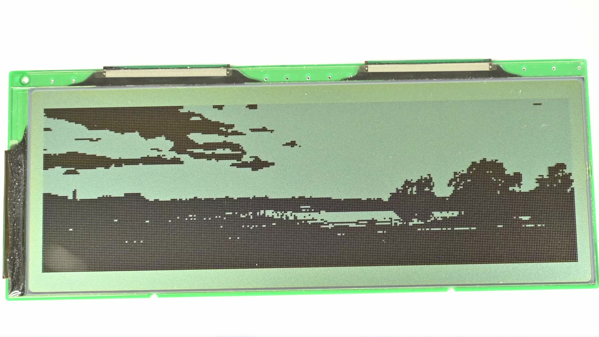
The issue is obvious, the screen is 1-bit monochrome, so for each pixel it could only be either on or off, without any gray shades in between. If I just directly display the image by clamping the pixel value to 0 or 1, it would look like this.
The good news is I could do better. Displaying images with a limited color palette is a well researched and understood topic, and one of the answers is to do dithering. The main idea is to use diffusion of available colors to create approximation of colors not available from the color palette. For example if I were to apply dithering to the image, it would look like this.
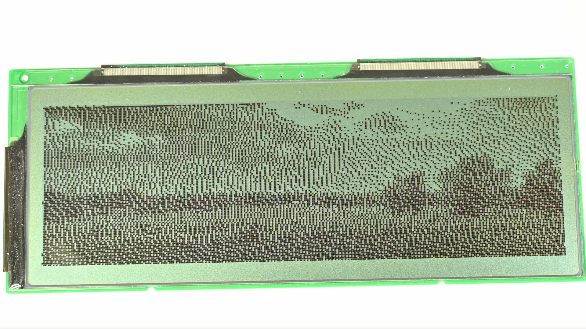
It’s still outputting to a 1-bit screen, but now I could see more details from the image compared to the direct clamping. There are many ways of doing the dithering, the one used here specifically is based on error diffusion. Let’s take a closer look.
Say I have an input image, that’s 8-bit grayscale, and output is 1-bit. Or in otherways, if to represent the output in the input range, the output could be either 0 or 255. Anything in the middle is unavailable. To choose the output value based on input, a quantizer is introduced here: if the input is larger than a half, or 127, then it outputs 255, otherwise 0. This is what I have been doing before, clamping the image to black or white directly.
Now bringin the error diffusion on to the table. Each time the quantizer chooses an output value that’s different from the input, an error is introduced. The error is simply the difference between input and output. In the previous case, the error is simply dropped. However, if the goal is to minimize the error, then I should do something to compensate for the error. Error-diffusion means to diffuse the error to neighboring pixels. As a result, when the quantizer quantized these pixels, the error would have a chance to be compensated. This is what I’ve shown you before.
But something is off, I remember these screens could do many levels of grayscale, like on these devices they could all display different shades of gray or green. However, almost all of the screens I got were 1-bit mono. Initially I thought this is probably because the screen I got was for industry control or similar stuff so they don’t need that. Only the screen for consumer electronics would have greyscale support. Which turned out to be false. I took apart some devices that have 16 levels of grayscale and found out that the screens themselves are 1-bit screens. What’s the trick there? Let’s take a deep dive into this.
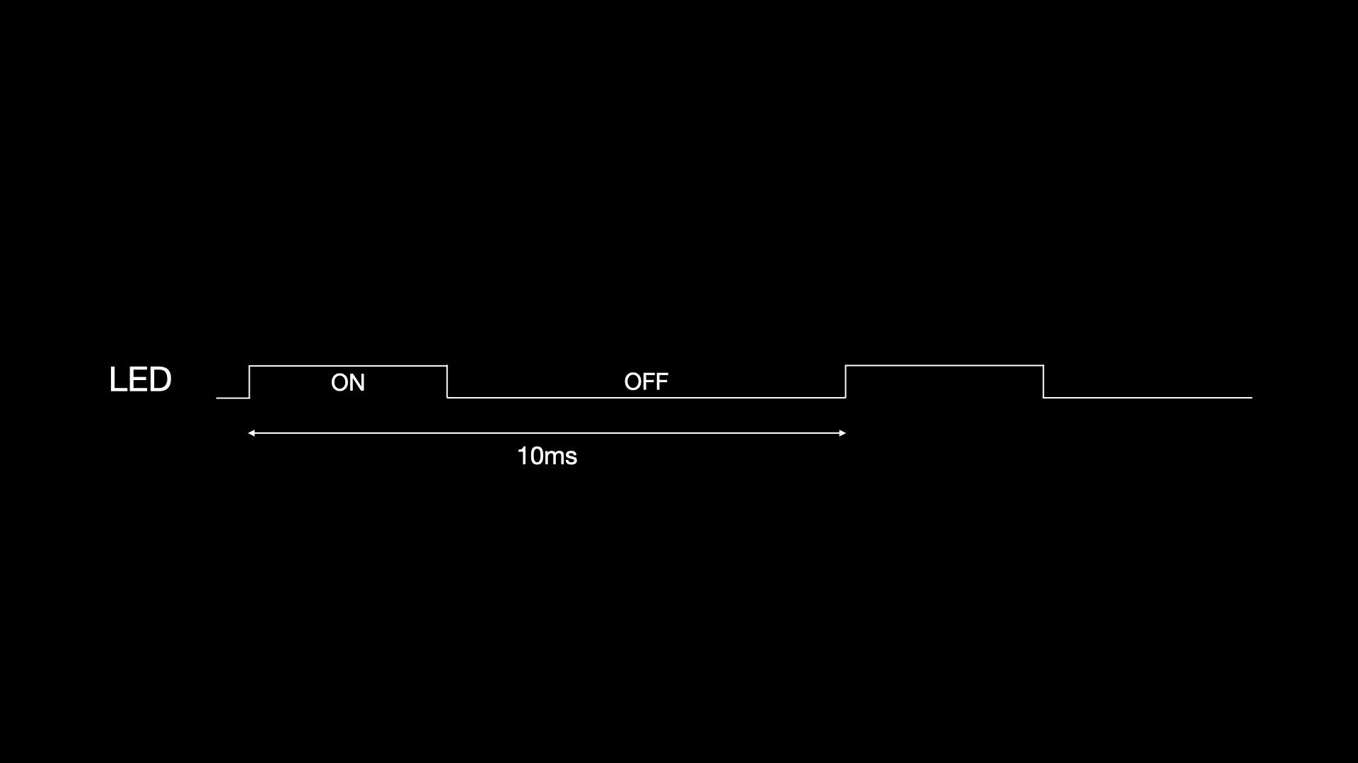
So now I am now given a screen that could either display black and white, and I would like to display different shades of gray on the screen. How to do that? Well if I use another analogy to that: I have a digital output pin which could be either high or low, and there is an LED connected to it. And instead of just lighting up or shutting off, I want to have a different brightness. Does this sound familiar? There is a commonly used technique called PWM for doing this. Basically define a period, and for some time in this period the output is high, and the rest is low. Then the whole period gets repeated over and over. If this is fast enough that eyes couldn’t detect, one would think it’s some brightness in the middle, instead of it being switched on and off rapidly.
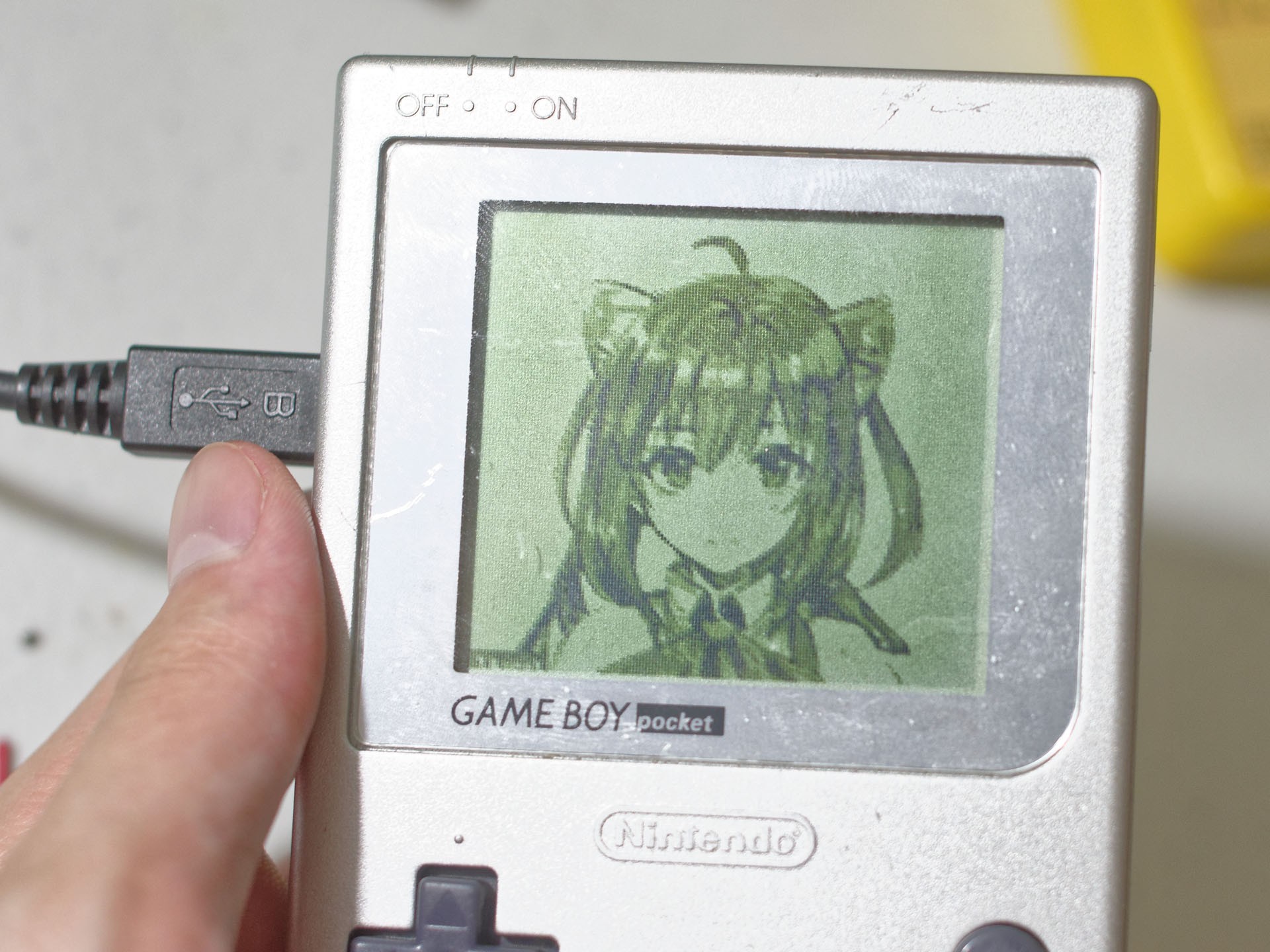
Can I do the same on these monochrome LCDs? Yes and no. There are some LCDs that have PWM built into the driver chip, so they natively take multiple bits per pixel as input, and would modulate the greyscale during the screen refreshing process. One example is that GameBoy’s screen takes 2 bit per pixel input natively and produces 4 level grayscale.
However based on my observation this is not that common, most other screens like the one on PDAs or old laptops typically only take 1-bit per pixel input and only do black and white natively.
Well then if the screen driver chip doesn’t have PWM built-in, can I still use PWM on a maybe higher level? You see, LCD, to keep display, needs to be constantly refreshed. So if I look at a single pixel, it’s being driven at a constant interval, and I have control over the level, being either high or low. In this sense, I could simply put a PWM waveform there.
For example, if I want 16 level grayscale, then I can have a PWM period of 15, then based on the output level, the duty cycle would be 0 to 15 cycles. Sounds great. Does it work? Let’s see.
To code it, there are 1 bit-per-pixel frame buffers that would be sent to the screen. And there are 8 bit-per-pixel frame buffers that would hold the grayscale image to be displayed. Now I just need to write a function that does the software PWM on these buffers.
So I set up a PWM period counter, which goes from 0 to 14, incrementing on each frame. Then in a loop, for each pixel, it compares the incoming pixel value with the counter value, if larger it outputs 1, otherwise 0. So with different pixel values it would output a different duty cycle on each pixel.
uint32_t framecnt = 0;

static inline uint8_t handle_pixel(uint8_t color) {
    return ((color / 16) > framecnt);
}

static void process_frame() {
    for (int i = 0; i < X *