


The introduction of automatically focusing lenses has changed photography in numerous ways. Autofocus systems have significantly improved the reliability and accuracy with which fast moving objects can be shot. Round four decades ago, the new level of convenience offered by autofocus lenses has made photography more accessible to the masses. Since their first release of an autofocus lens in 1981, Canon has constantly developed their lens technology using different approaches. Over time, Canon has introduced seven different autofocus motor technologies that will be presented here.
Canon Autofocus Systems
In optics, focus describes the point at which incoming light rays converge and it is used synonymously as a concept of sharpness. Autofocus, by contrast, is a technology to automatically focus the lens at a desired subject. The autofocus detection system inside the camera determines the ideal focusing lens position and instructs the lenses autofocus drive accordingly. In 1987, Canon has introduced the both the EOS camera system and EF lenses which have been designed with autofocus as standard features. There have been some Canon autofocus lenses available before that date, but these have been discontinued with the introduction of EF lenses. For this reason, this chapter focuses on all autofocus motor types that are used in EF, EF-S, RF, and RF-S lenses that are marketed still today.
The autofocus group of lens elements always shifts along the optical axis in a linear way. While focusing automatically, the movement is generated by some type of actuator. Autofocus actuators can basically be divided into two categories:
- Rotary Drive Systems: These generate a rotation that is translated into a linear sliding motion via precision mechanics. One common transmission type uses a focusing barrel with helical slots. The focusing group of lens elements is engaged with these slots and slides forwards or backwards axially when the helical slot barrel is turned. Another possible transmission type uses a lead screw with a lead nut that connects to the focusing group of lens elements.
- Linear Drive Systems: Also called direct-drive systems. These perform a sliding movement that does not have to be translated. The focusing group of lens elements is directly connected to the linear actuator.
The first types of autofocus drive systems used rotary movement and these include the Arc-Form Drive, Ring-Type USM, DC Micro Motor, Micro USM, Micro USM II, and Stepper Motor. Later, the switch was made to linear drives which include the Nano USM and the Voice Coil Motor.
The following comparison chart shows all of the autofocus drive types that have ever been used in Canon’s EF, EF-S, RF, and RF-S lenses. Note how the indication on lens barrels is often just USM but the exact type of built-in motor can be different. This is because Canon’s USM autofocus drive system comprises several different mechanism families, the ring-type USM, the Micro USM (I and II), and the linear Nano USM. All USM drives use piezoelectric technology but with some variations. If an autofocus Canon lens has no indication on its barrel about the autofocus technology used, the lens either has an AFD or DC Micro Motor installed. The date indicates when a particular type of motor was first used in a lens. While some of the early types like the Arc-Form Drive have been discontinued, most other types are still in use today. One key differentiator between these technologies is the capability of a lens to allow full-time manual (FTM) focus override. The ring-type ultrasonic Motor was the first autofocus system that allowed FTM focus override. Until 2012, most other lenses did not offer this type of manual focusing while autofocus is activated. The latest types of autofocus drives, including the Stepper Motor, Nano USM, and Voice Coil Motor, offer focus-by-wire. This is a concept where the manual focusing ring on the lens barrel is not mechanically coupled with the focusing group of lens elements but electronically controls the autofocus drive. Lenses that use focus-by-wire always offer full-time manual focus override.

Arc-Form Drive (AFD)
1987 – 1990
Originally, the designation AFD stood for autofocus drive. Later, when other autofocus drive systems were introduced, the term was changed into Arc-Form Drive.
The Shape
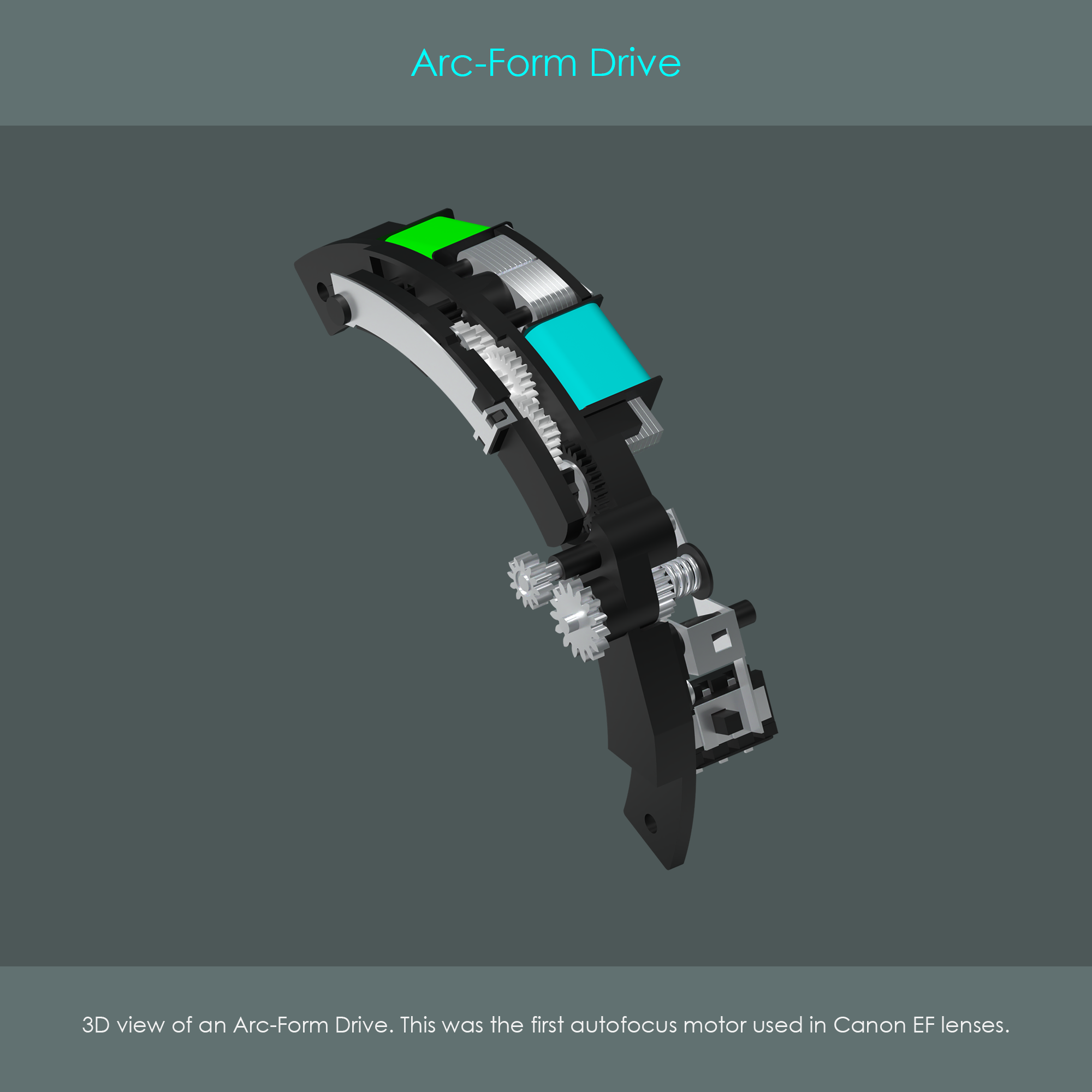
The Arc-Form Drive was the first autofocus motor that was used in EF lenses. The assembly included the motor unit, the gear drive, and a transmission that allowed the user to switch between manual focusing and autofocusing. The AFD assembly was shaped like an arc so that it could easily be installed inside a cylindrical lens barrel.
Lenses with Arc-Form Drives
- Canon EF 15mm F2.8 Fisheye (1987)
- Canon EF 24mm F2.8 (1988)
- Canon EF 28mm F2.8 (1987)
- Canon EF 35mm F2 (1990)
- Canon EF 50mm F1.8 (1987)
- Canon EF 50mm F2.5 Compact Macro (1987)
- Canon EF 135mm F2.8 Softfocus (1987)
Construction
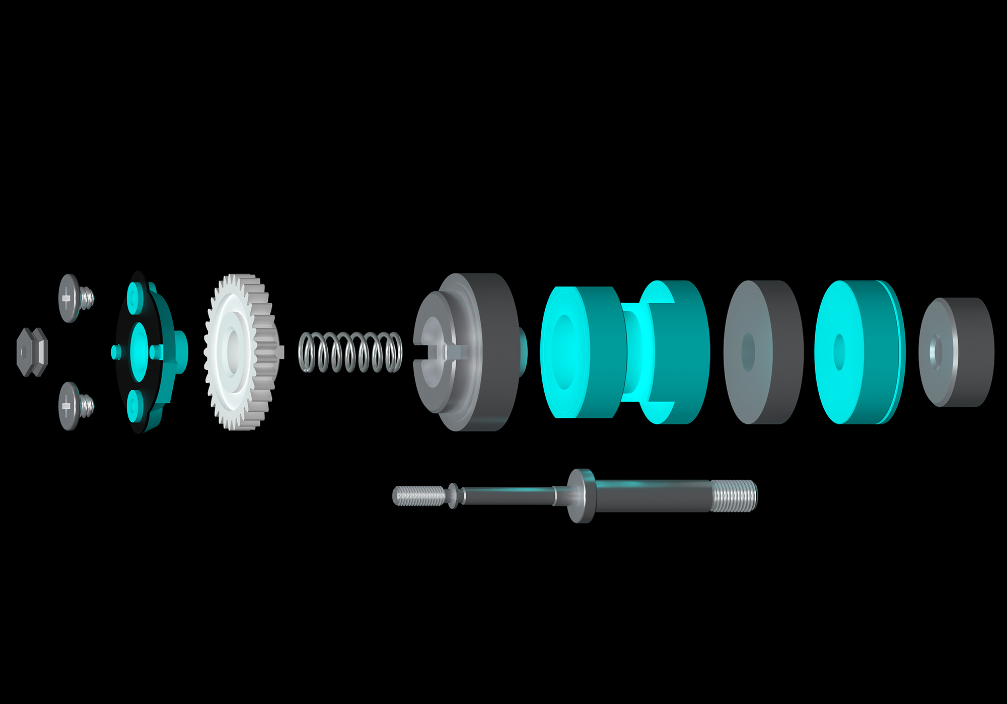
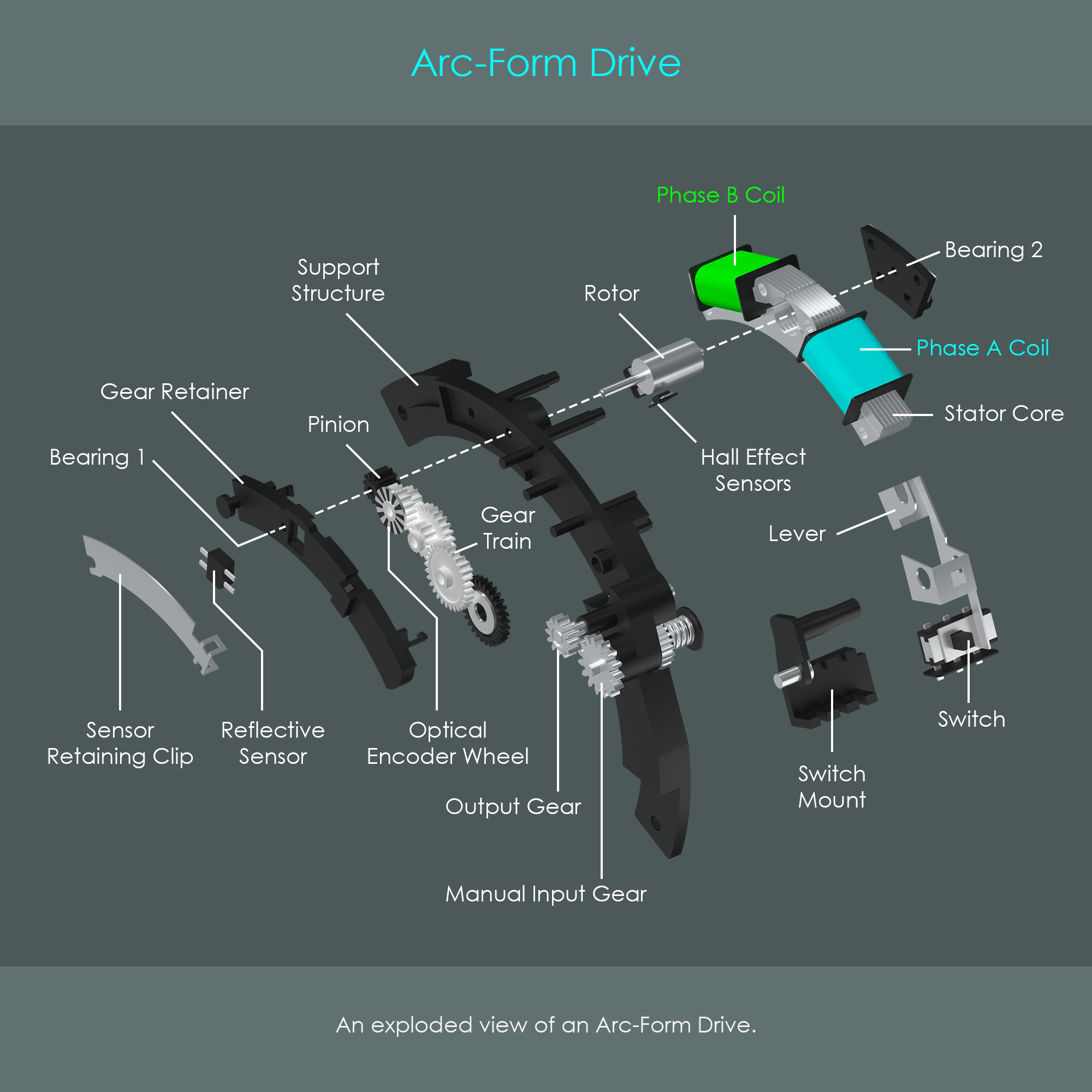
The illustration shows an Arc-Form Drive inside a Canon EF 50mm F2.5 Compact Macro lens. The unit is driven by a 2-phase bipolar asymmetric stepper motor that consists of a stator core, two electromagnetic coils (each coil is also referred to as a phase), and a permanent magnet rotor. The bipolar construction of the motor allows current to flow through each coil in both directions. The term asymmetric refers to the shape of the stator that is not rotationally symmetric as in conventional stepper motors (but it is axially symmetrical though).
The motor drives a reduction gear train that has the purpose of reducing the output gear’s speed but at the same time increase the torque of that gear. A lever is used to shift the output gear in one of two possible positions where it either engages with the gear train or with the manual input gear that is connected to the manual focusing ring of the barrel.
Two feedback systems are used to monitor the drive unit during operation. One system is used to confirm proper rotation of the rotor and another system is used to measure the number of turns the unit has performed:
- Two hall effect sensors are placed very closely at the rotor. These can detect changes in magnetic fields and are therefore used to confirm rotor movement.
- An optical encoder wheel with alternating black and reflective zones is attached to one of the gears. An infrared reflective sensor is placed so that it can read the number of steps that the encoder wheel turns (each transition between two zones is a step). This provides crucial feedback to the lens controller as autofocus instructions typically include a predefined number of steps an autofocus motor has to move into a certain direction.
Front View
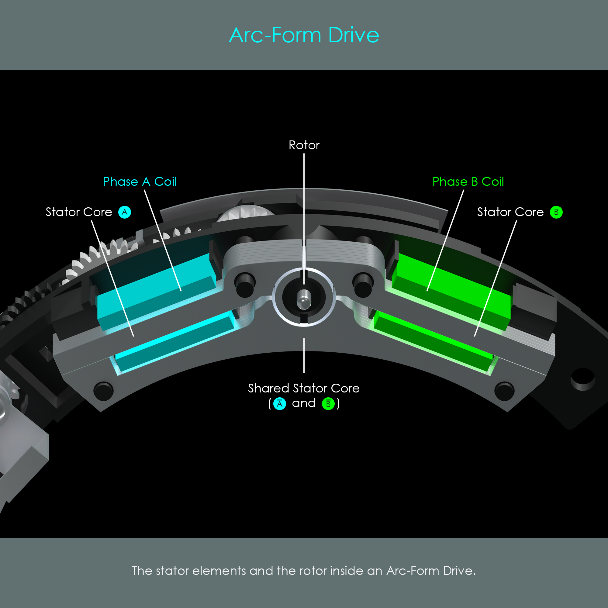
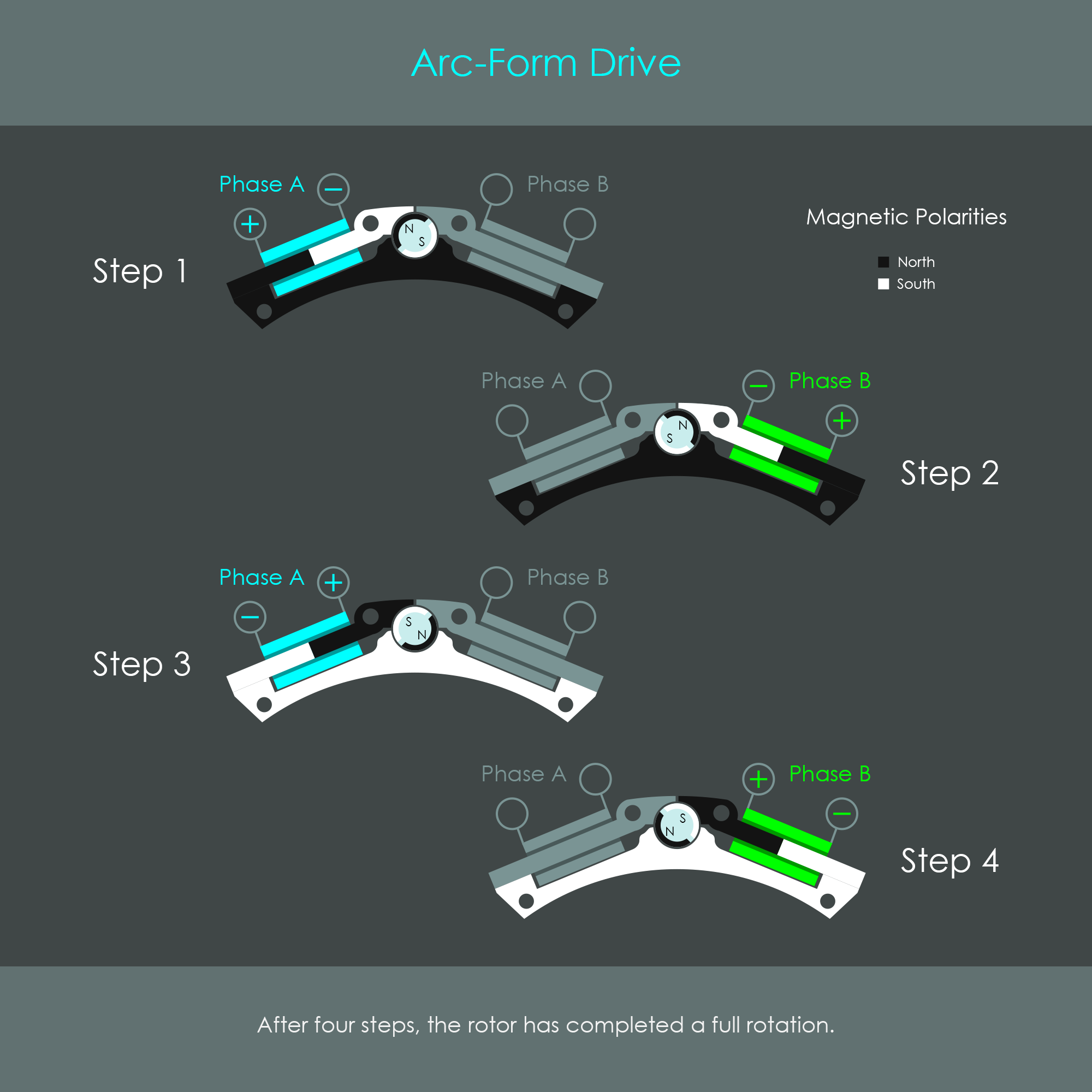
The illustration is a front view of the stepper motor with the cover removed. The rotor has two magnetic polarities opposite to each other, north and south. The stator consists of two phases that are colored in cyan and green for reasons of better explainability. The stator cores run through the phase coils to conduct the electromagnetic flux towards the rotor.
Stepper Motor Operation
During autofocus operation, the wire coils are excited via electrical impulses, which in turn magnetizes the stator core. The polarity of the voltage applied to the two coils is changed in a pre-defined sequence. The rotor performs a complete rotation in four steps:
- Phase B coil is turned off. Phase A coil is energized so that the left part of the stator core is magnetized, attracting the rotor to perform a rotation. (This is a 90 degree clockwise rotation if the previous step of the motor was step 4.)
- Phase A coil is turned off. Phase B coil is energized so that the right part of the stator core is magnetized. This attracts the rotor so that it performs a 90 degree clockwise rotation.
- Phase B coil is turned off. Phase A coil is energized with opposite polarity. This magnetizes the left part of the stator core again, but this time with opposite magnetic polarity. The rotor is attracted again so that it performs another 90 degree clockwise rotation.
- Phase A coil is turned off. Phase B coil is energized with opposite polarity. This magnetizes the right part of the stator core again, but this time with opposite magnetic polarity. This induces the rotor to perform another 90 degree clockwise rotation.
The sequence of steps is repeated as long as the rotor is required to turn. If the sequence is run in reverse from step 4 to step 1, the rotor turns counter-clockwise. The diagram summarizes these four steps.
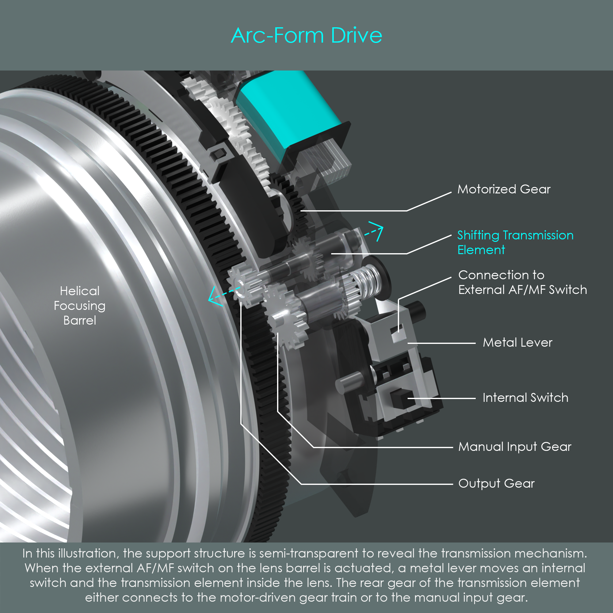
AFD Transmission
The AFD motor was designed with a transmission element that is also the output gear, the one that actually drives the helical focusing barrel. Note how the focusing barrel has a wide gear rim along its perimeter that allows the transmission element to shift a certain amount while always remaining engaged with the focusing barrel. The metal lever is connected to the MF/AF switch on the lens barrel and it shifts the transmission element so that it connects the output gear either with the motorized gear train or with the manual input gear. If the output gear is connected to one option, it is disengaged from the other option. For that reason, the Arc-Form Drive does not have full-time manual focus override available.
In terms of overall performance and usability, the Arc-Form Drive is considered to be noisy during operation and slower than other autofocus drives. When following moving subjects, the system shows a noticeable reaction time. Lenses with an Arc-Form Drive have to sequentially focus and then stop down the aperture diaphragm. All other lenses with different autofocus motors are able to operate the autofocus motor and aperture diaphragm at the same time. Despite these weaknesses, AFD lenses still offer reliable autofocusing performance.
Ring-Type Ultrasonic Motor (USM)
1987 – Present
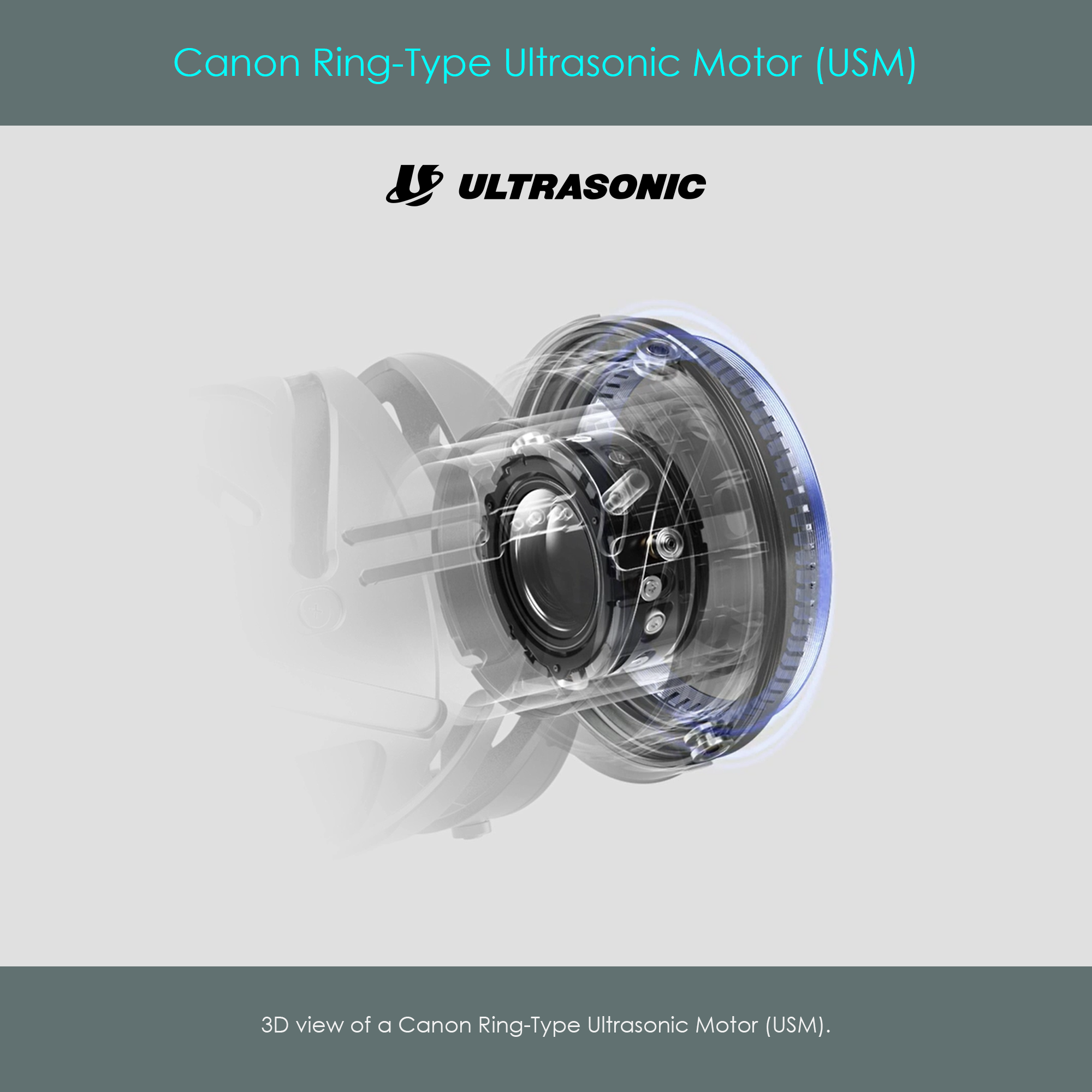
Canon’s ultrasonic motors are very exceptional types of actuators. They neither have electromagnetic coils or magnetic rotors, so their motion is not generated by magnetism like in traditional motors. Instead, they use an ingenious combination of piezoelectric effects and friction. Introduced in November 1987 with the Canon EF 300mm F2.8L USM lens, the ring-type USM was the first implementation of this piezoelectric technology in photographic lenses, and in the years that followed, some different types of USM drives would appear.
Canon’s ring-type ultrasonic motor – as the name suggests – is shaped like a ring and, for that reason, fits perfectly inside the lens barrel. The optical system of the lens runs through the opening of that construction. At the time of its advent, this new technology was groundbreaking in its design and functionality, being ultra-fast and silent. They provide a high level of torque powerful enough to move even heavy groups of focusing lens elements inside super-telephoto lenses. Due to their high torque, no speed-reducing gear train is required when connecting the motor to the focusing mechanism. The ring-type USM has high holding torque maintained at zero input power and offers low inertia from its rotor providing rapid start and stop characteristics. In addition, this type of drive technology is unaffected by electromagnetic fields.

Ring-Type USM Main Parts
The ring-type USM can be divided into the rotor, the piezoelectric stator, and various support rings.
- The rotor is the only part of this motor that actually rotates around the optical axis while the USM is in operation. The rotor itself is a compound of metal and plastic parts bonded together. The rotor has a sliding rail on the side facing the stator.
- The stator is an elastic metal body. In this context, elastic refers to the ability of the stator to oscillate to a certain extent, similar to a tuning fork. The stator has a ring of piezoelectric ceramic elements welded to its back (away from the rotor). Once this layer is electrically excited, it sets the stator into vibration. The vibrational energy is then transferred into the rotor via friction. Apart from its vibration, the stator does not move.
- A felt ring is used to protect the sensitive piezoelectric layer from the metal support rings that are pressed against the stator, and to dampen the vibrations from being transmitted into the lens barrel.
- The ring-type USM motor only works when the stator is firmly pressed against the rotor. The compression spring is what exerts this pressure on both the stator and rotor. This spring is an important part that ensures proper functionality of the ring-type USM.
- the lock ring is an interface part that holds all parts of the unit tightly together. Three indents on the inner circumference of the lock ring slide into slots of an inner lens barrel, securing the ring in place.
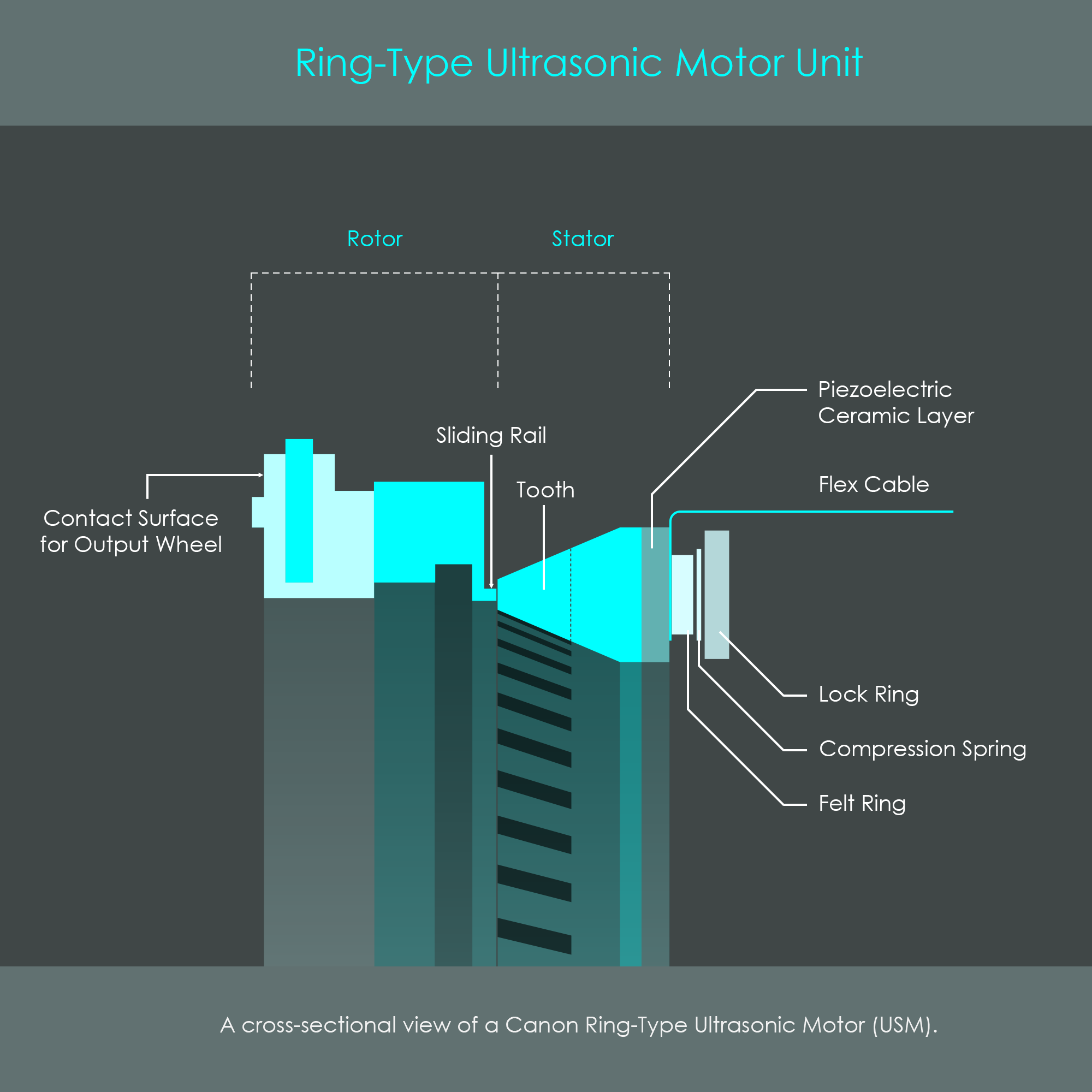
Ring-Type USM Details
The following illustration is a cross-sectional view of the ring-type USM when it is fully assembled. The piezoelectric layer is what generates vibrations. A flex cable connects the piezoelectric elements with the lens circuit board, and therefore provides power to this element. Once the unit is installed inside a lens barrel, a dedicated contact surface on the rotor pushes against wheels on an output ring (not shown in this illustration) that ultimately drives the focusing mechanism.
The compression spring creates a tension that is also referred to as preload force. Flat surface finishes of the sliding rail and the stator teeth ensure a good friction coefficient between rotor and stator. The preload force and the friction between the rotor and the stator determine the passive holding torque of the motor at zero power input.
Stator Size
Canon uses stator rings of two different sizes. The medium sized stator has an outer diameter of 62 mm, and the larger sized stator has an outer diameter of 77 mm. There is a huge number of Canon lenses that use ring-type ultrasonic motors as their autofocus drives. The following list is only a very short excerpt:
Stator Diameter 62 mm
- Canon EF 24mm F1.4 L USM
- Canon EF 50mm F1.2 L USM
- Canon EF 100mm F2 USM
- Canon EF 200mm F2.8 L II USM
Stator Diameter 77 mm
- Canon EF 400mm F2.8 L IS USM
- Canon EF 600mm F4 L IS USM
The Piezoelectric Ceramic Ring
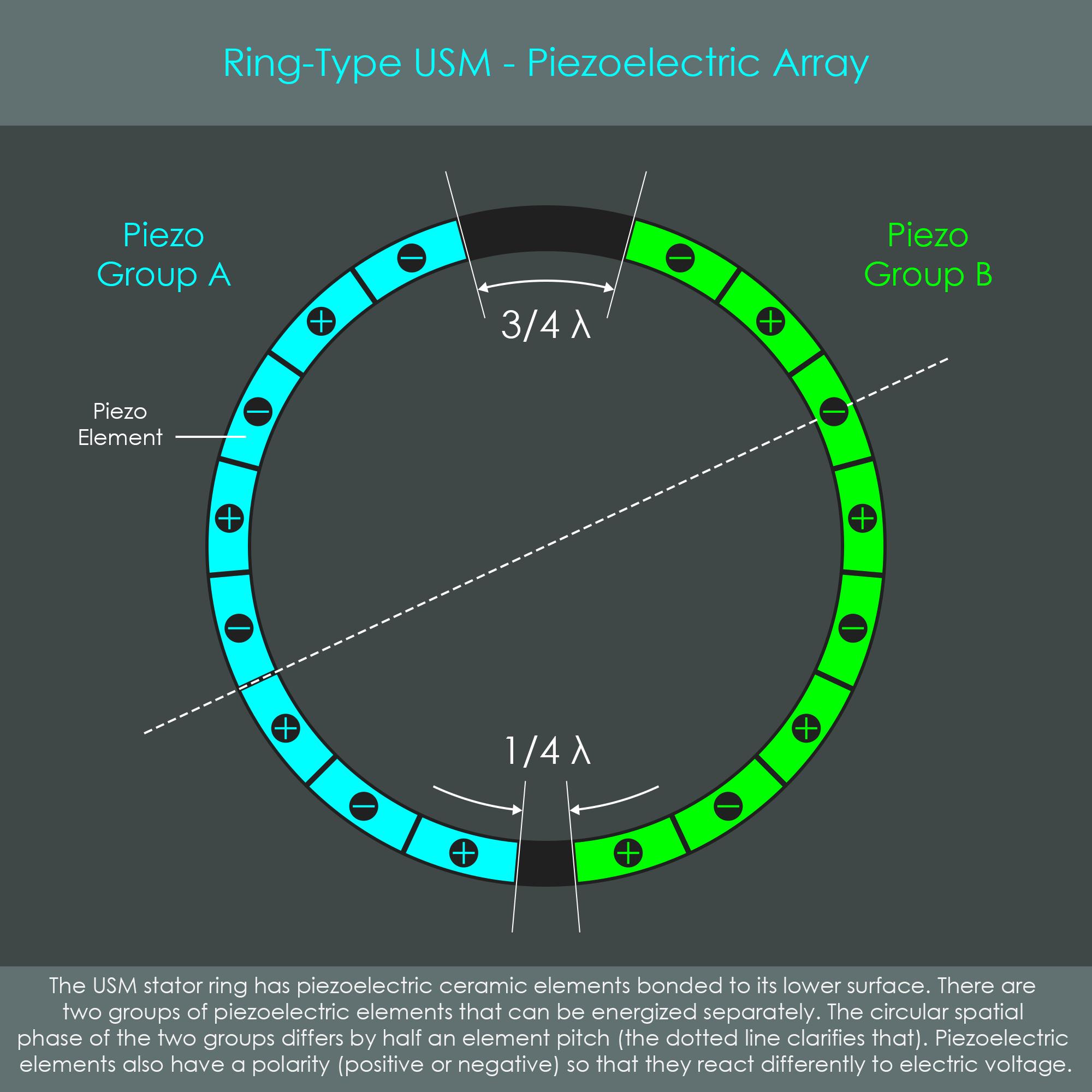
The operation of the motor requires the stator to vibrate in a very precise way. This vibration is generated by a segmented piezoelectric ceramic ring that is welded to the back of the elastic stator body. The illustration of the piezoelectric array shows the distribution and configuration of piezo elements on the ring.
The individual piezo elements are grouped together into groups A and B. Each group can be energized individually, and set the ring into vibration to form a standing wave with wavelength λ. Two piezo elements cover one full wavelength λ, and therefore each single piezo element has a length of λ/2. One of the key factors to ensure proper wave excitation in the stator is that both piezo groups are offset by λ/4 as shown in the illustration. This is also referred to as a spatial phase shift of λ/4.
Piezo Elements
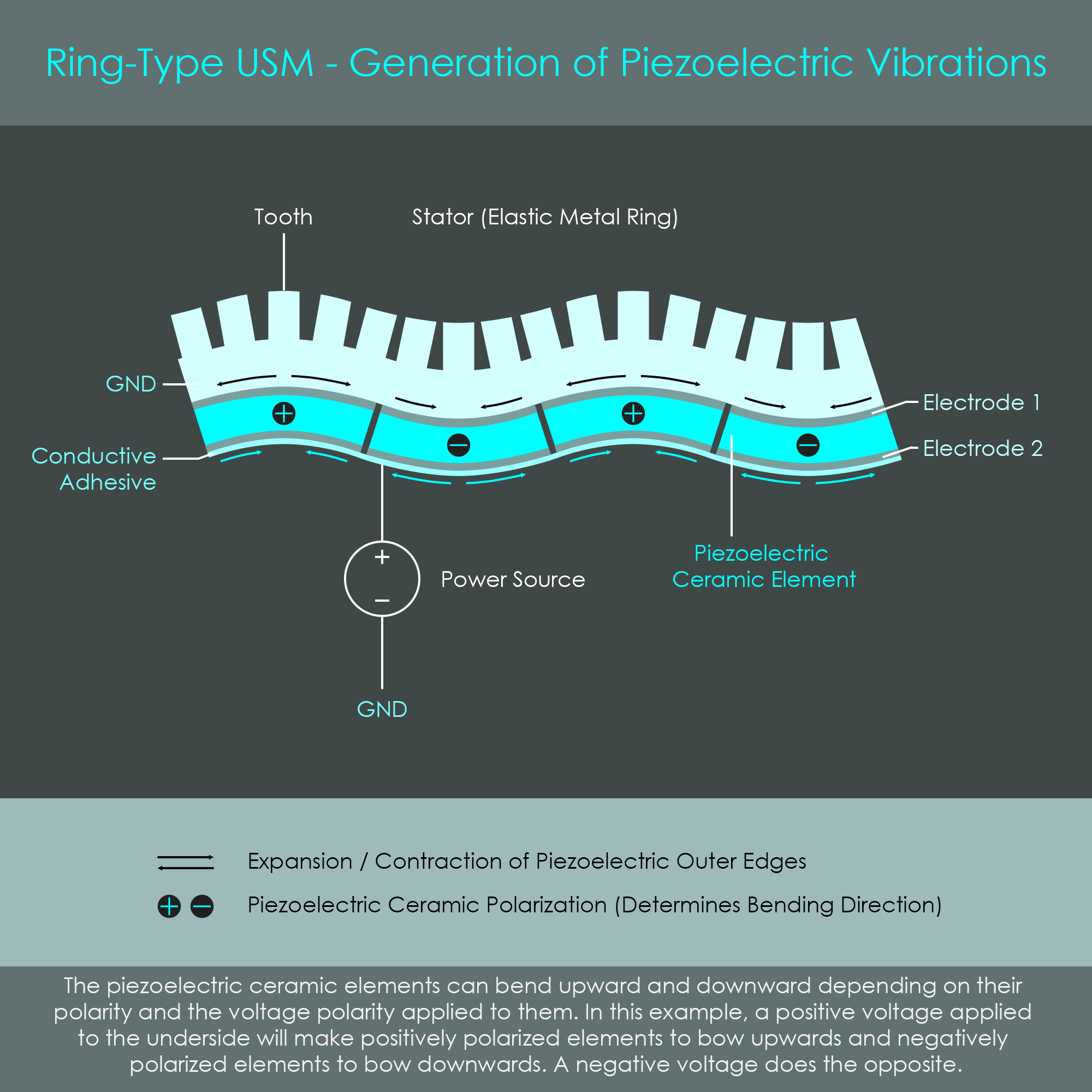
Piezoelectric ceramic elements are sandwiched between two electrodes. Electrode 1 is in direct contact with the metal stator ring and serves as ground (GND). In the following illustration, the lower electrodes of all piezo elements are covered by a layer of silver conductive adhesive so these elements are electrically connected to one group.
The piezoelectric ceramic elements have the property to deform when an electrical field is applied, an effect also described as the inverse piezoelectric effect. The direction in which piezo elements deform is defined by their piezoelectric polarization, expressed via positive and negative signs in this slightly simplified diagram. Depending on the polarity of the voltage applied across the electrodes, the individual piezo elements bend upwards or downwards. As piezo elements are arranged with alternating piezoelectric polarities, energizing the piezoceramic layer shapes the stator into a waveform. When the electrodes are subject to an alternating voltage of high frequency, the stator ring begins to oscillate. The amplitude of these oscillations is as small as 1-2 µm.
Piezo Group A is Energized
For the sake of better understanding, the two piezoelectric groups are viewed from the top, and energized separately. Piezo group A is fed by a distinct sinusoidal voltage (phase A) while piezo group B remains de-energized. This not only generates a standing wave across group A but the wave unfolds across the entire stator ring. Looking at a snapshot in time, hollow circles indicate valleys in the stator, whereas solid black circles indicate peaks in the stator. Note how the peaks and valleys are exactly at the center of each piezo element of group A, whereas on the opposite side of the ring, peaks and valleys are exactly between the piezo elements. Over the course of one sine oscillation, peaks will turn into valleys and back into peaks. At the same time valleys turn into peaks and back into valleys. A clear standing wave is formed only if the excitation frequency is equal to the natural flexural vibration resonant frequency of the stator. The resonant frequency of Canon’s ring-type USM is approximately 27,000 Hz (oscillations per second). This frequency is in the ultrasonic range, which is why this type of autofocus technology is called ultrasonic. Enlarging the illustration shows an animation of phase A generating a standing wave.
Piezo Group B is Energized
Now piezo group B is fed by a distinct sinusoidal voltage (phase B) while piezo group A remains de-energized. Again, a standing wave is generated and unfolds across the entire stator ring. This time, peaks (hollow circles) and valleys (solid black circles) are at the center of each piezo element of group B, whereas on the opposite side of the ring, peaks and valleys are exactly between the piezo elements. This shows that the two standing waves generated by group A and B are not congruent. Enlarging the illustration shows an animation of phase B generating a standing wave.
Both Groups are Energized
When both piezo groups are energized at the same time, their vibration-induced standing waves are combined and form a new wave. When phase A and phase B are shifted by a quarter of a sine wavelength λ – called a temporal phase shift of λ/4 – the resulting wavelength is a traveling wave. This temporal phase shift can be achieved, for example, by using a sine wave for phase A and a cosine wave for phase B. Unlike a standing wave, the peaks and valleys of a traveling wave move around the circumference of the stator ring similar to waves on the surface of water. This traveling wave is the source of the motor’s rotational energy. Enlarging the illustration shows an animation of both phases generating a traveling wave.
The sign of the temporal phase shift determines the propagating direction of the traveling wave, and consequently also the rotating direction of the rotor. The stator has teeth cut into the material, and these are designed to amplify the movement of the ring.
Feedback Control System
Not all piezo elements on the stator ring are used to generate waves. One small piezo element is located between the wave-generating piezo groups A and B and it serves as a sensor to measure the intensity of stator oscillations. Like all other piezo elements, the sensor element is sandwiched between two electrodes 1 and 2 (not shown in the illustration). Electrode 1 is directly connected to the metal stator body and serves as ground, whereas electrode 2 is on the opposite side and connects to the sensor line.
It was described earlier that applying a voltage to a piezo element generates a deformation of that element, referred to as the inverse piezoelectric effect. The actual (non-inverted) piezoelectric effect, however, is that pressure or deformation (such as bending) of the piezo element will generate an electric voltage. Consequently, the piezo’s electrical output reflects the wave amplitude of the stator at its location. This signal is picked up by the control circuitry and can be used to adjust
9 Comments
ExAr
Hi there!
I have written an e-book about all autofocus motor types used in Canon EF & RF lenses from the past 40 years.
chaosprint
Canon's lenses are great, but they're really expensive. The camara body itself has the same issue.
Sony seems to be the first choice for indie filmmakers and youtubers right now.
L-mount and M43 also seem to have great potential as Panasonic supports Phase Detection Autofocus.
edit:
There is no need to be cynical here. Market figures are cruel. I hope they are all good. Competition is the best. I should also mention the return of Nikon. The patent threshold of RAW such as RED is what we need to oppose.
liotier
As a Canon user since the mid-80's, I found this fascinating reading.
Edit: Wow – there's a whole collection of Canon lens technology articles there: https://exclusivearchitecture.com/03-technical-articles-CLT-…
myself248
Oh neat! I have a Newscale micro motor demo kit from years ago, and I wondered if they were ever successful in the market. But that hip-gyrating Micro USM action sure looks familiar.
actionfromafar
Cannot scroll pages in Firefox.
michh
I’ve recently been shooting film with an old EOS camera from the 90s I bought used and it was really nice being able to use the EOS lenses I bought for my DSLR in the 2000s and 2010s. It’s a dying standard now but it’s really impressive it lasted as long as it has, with significant technological innovation on both sides of the lens mount while retaining full compatibility. A brand new EOS EF lens still works with an 80s camera and a new 80D from 2017 can still use the lenses from the 1980s without any adapter. 30 years ain’t bad for a standard!
PaulHoule
I was a big fan of USM lenses when I had a Canon, but I had one go bad with fungus or something and for a while had only a 35mm prime which I even used to take pictures of birds. Then I lost my Canon and decided to get a Sony circa 2019 or so because all the reviews I saw for Nikon and Canon said the autofocus sucked on entry-level full frame cameras.
MartijnBraam
I've always wanted to know how the various autofocus systems worked. This page is incredible. I wish there was another one with the Nikon autofocus systems since that's what I actually have.
I still have several lenses with autofocus that don't have an AF motor in it at all, the motor is in the camera body instead there's a tiny screw on the lens mount that transfers the motor rotation to the autofocus parts in the lense. This was very slow and noisy though on my cameras.
exar0815
I always wanted to build a controller for Canon Telephoto lenses to use them with c-mount cameras and control the focus from a PC. Might be helpful for that.