

If you’ve been following along our USB-C saga, you know that the CC wire in the USB-C cables is used for communications and polarity detection. However, what’s not as widely known is that there are two protocols used in USB-C for communications – an analog one and a digital one. Today, let’s look at the analog signalling used in USB-C – in part, learn more about the fabled 5.1 kΩ resistors and how they work. We’ll also learn about emarkers and the mysterious entity that is VCONN!
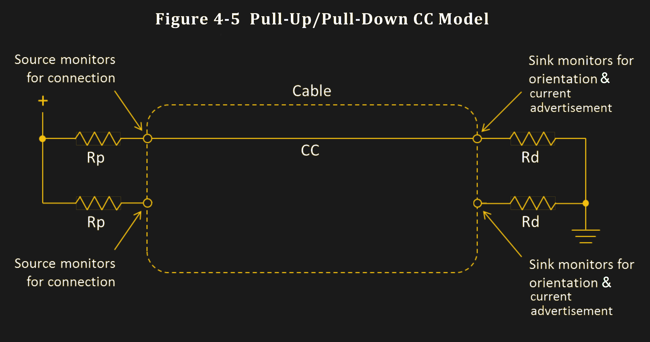
USB-C power supply expects to sense a certain value pulldown on the CC line before it provides 5 V on VBUS, and any higher voltages have to be negotiated digitally. The PSU, be it your laptop’s port or a charger, can detect the pulldown (known as Rd) because it keeps a pullup (known as Rp) on the CC line – it then checks if a voltage divider has formed on CC, and whether the resulting voltage is within acceptable range.
If you plug a device that doesn’t make a pulldown accessible through the CC wire in the cable, your device will never get power from a USB-C port, and would only work with a USB-A to USB-C cable. Even the smarter devices that can talk the digital part of USB-C are expected to have pulldowns, it’s just that those pulldowns are internal to the USB-C communication IC used. A USB-C port that wants to receive power needs to have a pulldown.
This part is well-known by now, but we’ve seen lack-of-resistor failures in cheap devices aplenty, and the colloquial advice is “add 5.1 kΩ resistors”. You might be afraid to think it’s so simple, but you’d be surprised.
Pullups, Pulldowns, And The Resulting Voltage Divider
There are two kinds of power roles for USB-C ports – supply side and consumer side. The analog side of USB-C lets designers add a simple way to negotiate power requirements when using USB-C at 5 V, without using specific or expensive ICs – using pullups for sources and pulldowns for sinks. The combination of a pullup and a pulldown forms a voltage divider, and the voltage itself represents the charger’s current capability.
 Now, in analog signaling mode, the source may adjust the pullup based on the power budget available to it, and that’s quite useful. Imagine a laptop or a charger with multiple USB-C ports. As each port gets loaded, there will be less current to give to other ports, which is in large part defined by how the device is built internally. Take the Framework laptop, for instance, which is equipped with four USB-C ports. Each port can provide 15 W at 5 V / 3 A, but if you want to power four sink-only USB-C devices at once, it will only be able to give 1.5 A on third and fourth port – quite a reasonable limitation from an engineering perspective.
This means that higher-consumption devices, like 1.5 A and 3 A max devices, are expected to monitor the voltage on the CC line to determine whether they might exceed the power budget by adjusting their power demands, or otherwise getting shut down if the newly established current limit is exceeded.

What does this mean for you as a user? Nothing, if your devices are low-power enough. Your devices are expected to monitor the voltage on the CC line and adjust their appetite accordingly. Some storebought devices won’t do that, but it’s rare. As a hacker? If you build a device that gets power from a USB-C port and you aim to get full 3 A at 5 V, remember that not all USB-C ports will provide you with that. You can, however, check for 3 A availability by measuring the voltage on the CC line. Or don’t, I’m not your mom, and many a hacker device thrives with zero detection.
What voltages can you expect on the CC line? Well, it’s the kind of voltage you can read with a basic ADC that your microcontroller has, or even a comparator.
As you can see, it’s all under 3.3 V so you won’t need a voltage divider if you’re using a full-swing microcontroller ADC. Oh, and if a USB-C socket is what you have, remember to monitor both CC pins separately, of course.
Do I Really Have To?
Do you really need to monitor the CC voltage? When you’re just hacking away at something, not really, but it can help if you do when you want to go beyond 0.5 A – 1 A. If you exceed the current demands that the source port can provide, it is supposed to simply stop supplying power to your device – a pretty safe outcome. On the other hand, the USB-C philosophy is to have multiple layers of safeguards, and if you’re building a 15 W device with the simple 5.1 kΩ resistor approach, you might as well make it be a device that can detect its power supply being insufficient. Also, it’s quite easy to do!
Otherwise, you can just ex