

Introduction
Ask somebody in the building industry to visually communicate the architecture of a building and you’ll be presented with site plans, floor plans, elevation views, cross-section views and detail drawings.
In contrast, ask a software developer to communicate the software architecture of a software system using diagrams and you’ll likely get a confused mess of boxes and lines …
inconsistent notation (colour coding, shapes, line styles, etc), ambiguous naming, unlabelled relationships, generic terminology, missing technology choices, mixed abstractions, etc.
As an industry, we do have the Unified Modeling Language (UML), ArchiMate and SysML,
but asking whether these provide an effective way to communicate software architecture is often irrelevant because many teams have already thrown them out in favour of much simpler “boxes and lines” diagrams.
Abandoning these modelling languages is one thing but, perhaps in the race for agility, many software development teams have lost the ability to communicate visually.
Maps of your code
The C4 model was created as a way to help software development teams describe and communicate software architecture, both during up-front design sessions and when retrospectively documenting an existing codebase.
It’s a way to create maps of your code, at various levels of detail, in the same way you would use something like Google Maps to zoom in and out of an area you are interested in.

Level 1: A System Context diagram provides a starting point, showing how the software system in scope fits into the world around it.

Level 2: A Container diagram zooms into the software system in scope, showing the high-level technical building blocks.
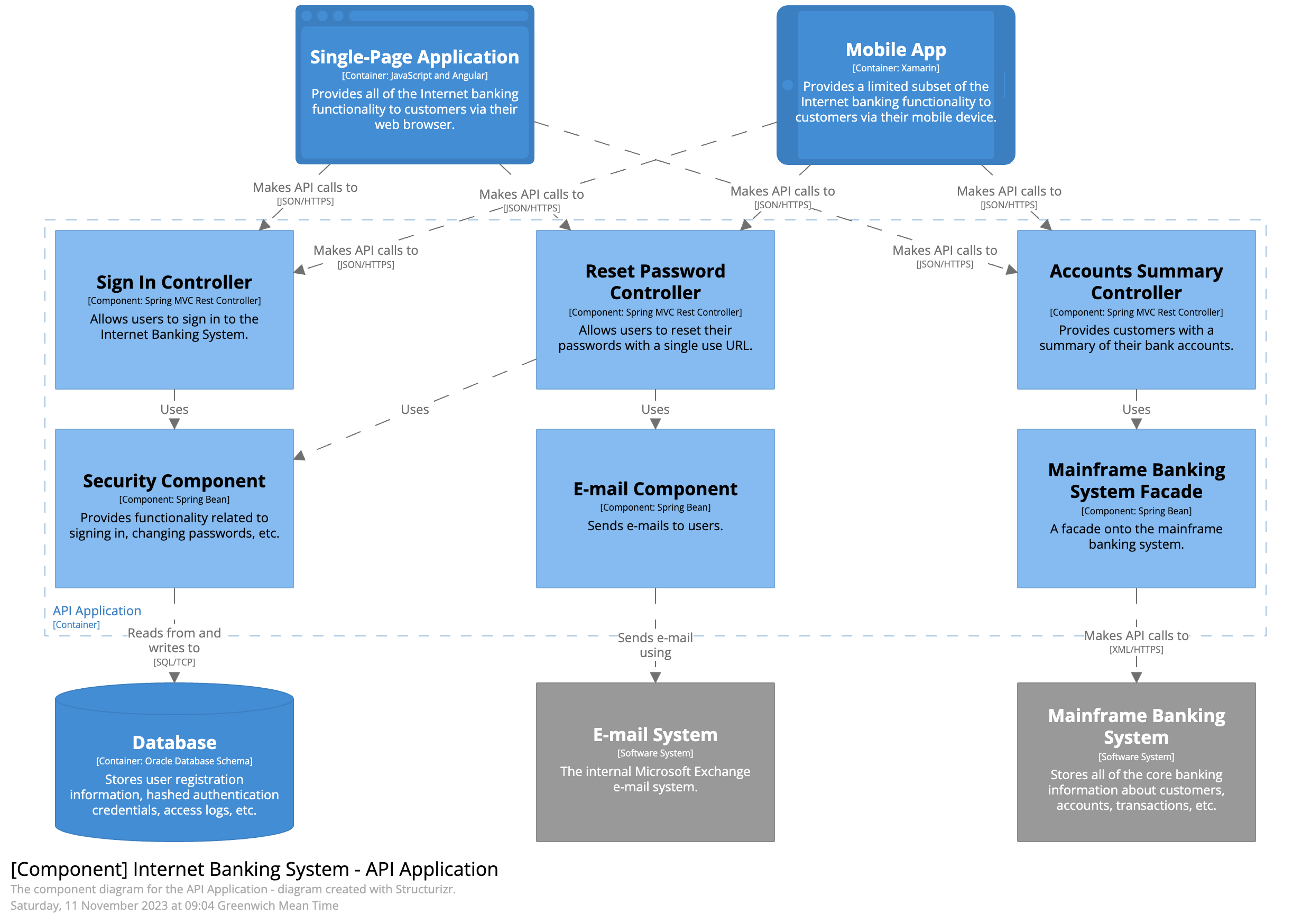
Level 3: A Component diagram zooms into an individual container, showing the components inside it.

Level 4: A code (e.g. UML class) diagram can be used to zoom into an individual component, showing how that component is implemented.
The C4 model is an “abstraction-first” approach to diagramming software architecture, based upon abstractions that reflect how
software architects and developers think about and build software. The small set of abstractions and diagram types makes the C4 model
easy to learn and use.
Please note that you don’t need to use all 4 levels of diagram; only those that add value – the System Context and Container diagrams are sufficient for many software development teams.
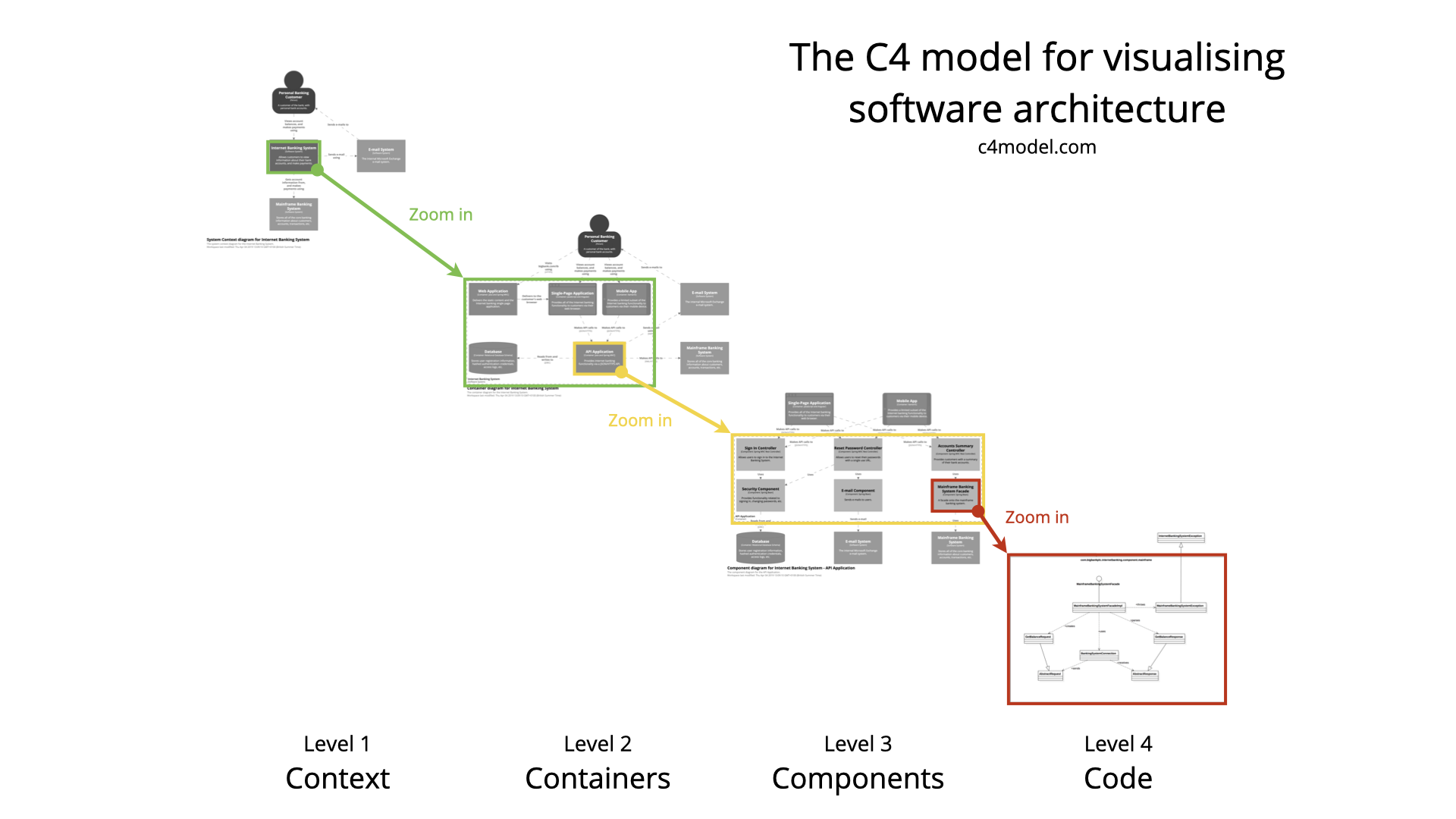
Different levels of zoom allow you to tell different stories to different audiences.
Hover your mouse over the diagram, find elements with a  , and double-click to zoom-in.
Abstractions
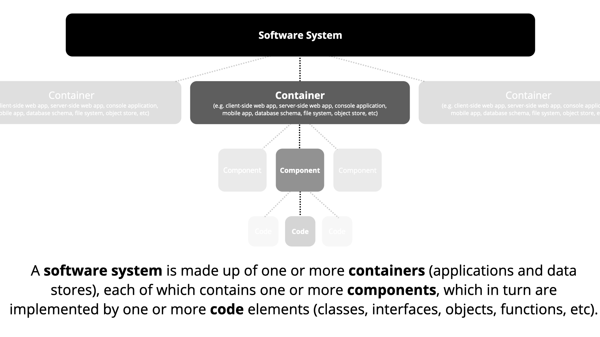
In order to create these maps of your code, we first need a common set of abstractions to create a ubiquitous language that we can use to describe the static structure of a software system.
A software system is made up of one or more containers (applications and data stores),
each of which contains one or more components,
which in turn are implemented by one or more code elements (classes, interfaces, objects, functions, etc).
And people may use the software systems that we build.
Person
A person represents one of the human users of your software system (e.g. actors, roles, personas, etc).
Software System
A software system is the highest level of abstraction and describes something that delivers value to its users, whether they are human or not. This includes the software system you are modelling, and the other software systems upon which your software system depends (or vice versa).
In many cases, a software system is “owned by” a single software development team.
Container (applications and data stores)
Not Docker! In the C4 model, a container represents an application or a data store. A container is something that needs to
be running in order for the overall software system to work. In real terms, a container is something like:
- Server-side web application: A Java EE web application running on Apache Tomcat, an ASP.NET MVC application running on Microsoft IIS, a Ruby on Rails application running on WEBrick, a Node.js application, etc.
- Client-side web application: A JavaScript application running in a web browser using Angular, Backbone.JS, jQuery, etc.
- Client-side desktop application: A Windows desktop application written using WPF, an OS X desktop application written using Objective-C, a cross-platform desktop application written using JavaFX, etc.
- Mobile app: An Apple iOS app, an Android app, a Microsoft Windows Phone app, etc.
- Server-side console application: A standalone (e.g. “public static void main”) application, a batch process, etc.
- Serverless function: A single serverless function (e.g. Amazon Lambda, Azure Function, etc).
- Database: A schema or database in a relational database management system, document store, graph database, etc such as MySQL, Microsoft SQL Server, Oracle Database, MongoDB, Riak, Cassandra, Neo4j, etc.
- Blob or content store: A blob store (e.g. Amazon S3, Microsoft Azure Blob Storage, etc) or content delivery network (e.g. Akamai, Amazon CloudFront, etc).
- File system: A full local file system or a portion of a larger networked file system (e.g. SAN, NAS, etc).
- Shell script: A single shell script written in Bash, etc.
- etc
A container is essentially a context or boundary inside which some code is executed or some data is stored.
And each container is a separately deployable/runnable thing or runtime environment, typically (but not always) running in its own process space.
Because of this, communication between containers typically takes the form of an inter-process communication.
Component
The word “component” is a hugely overloaded term in the software development industry, but in this context a component is a grouping of related functionality encapsulated behind a well-defined interface.
If you’re using a language like Java or C#, the simplest way to think of a component is that it’s a collection of implementation classes behind an interface. Aspects such as how those components are packaged (e.g. one component vs many components per JAR file, DLL, shared library, etc) is a separate and orthogonal concern.
An important point to note here is that all components inside a container typically execute in the same process space.
In the C4 model, components are not separately deployable units.
Notation
The C4 model is notation independent, and doesn’t prescribe any particular notation.
As a starting point though, a simple notation that works well on whiteboards, paper, sticky notes, index cards and a variety of diagraming tools is as follows.

Person
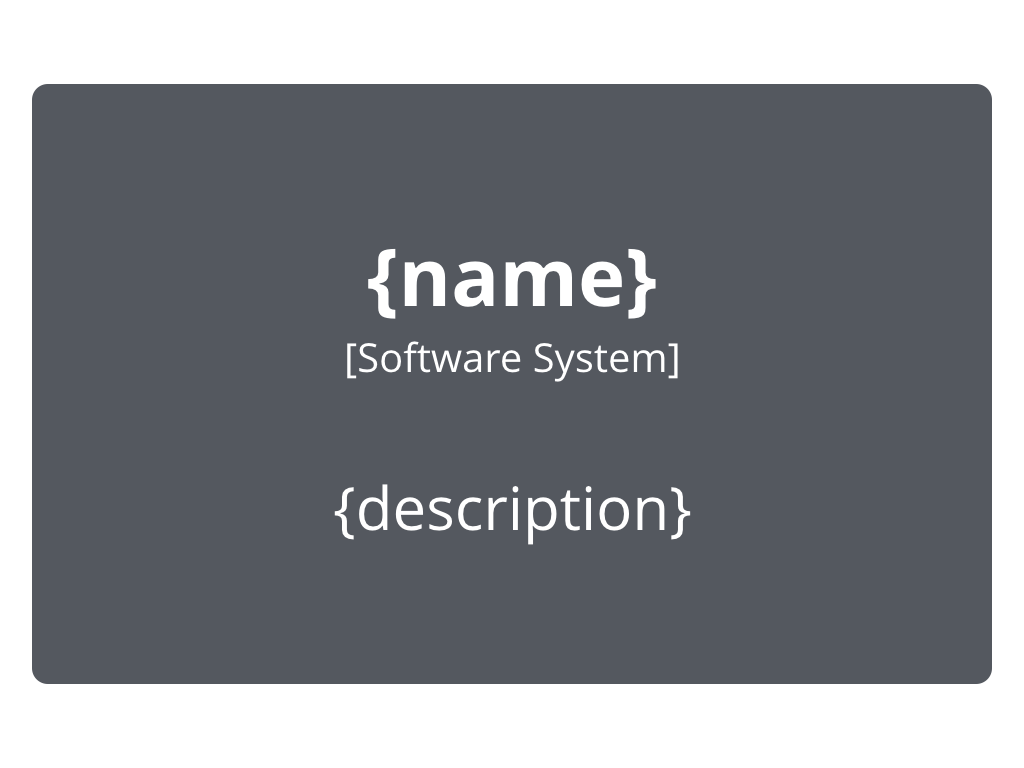
Software System
Container
Component

Relationship
You can then use colour and shapes to supplement the diagram, either to add additional information or simply to make the diagram more aesthetically pleasing.
C4 and UML
Although the example diagrams above are created using a “boxes and lines” notation,
the core diagrams can be illustrated using UML with the appropr